Rotor blade for a second phase of a compressor

a compressor and blade technology, applied in the direction of marine propulsion, vessel construction, other chemical processes, etc., can solve the problems of friction loss, influence on the distribution of limit layers along the walls,

Active Publication Date: 2008-02-21
NUOVO PIGNONE TECH SRL
View PDF24 Cites 26 Cited by
  • Summary
  • Abstract
  • Description
  • Claims
  • Application Information

AI Technical Summary

Benefits of technology

[0017]Further characteristics of the invention are indicated in the subsequent claims.

Problems solved by technology

This depends on the fact that the geometric characteristics of the blade cause a distribution of the relative velocities in the fluid, consequently influencing the distribution of the limit layers along the walls and ultimately, losses due to friction.

Method used


Image

  • Rotor blade for a second phase of a compressor
  • Rotor blade for a second phase of a compressor
  • Rotor blade for a second phase of a compressor

Examples


Embodiment Construction

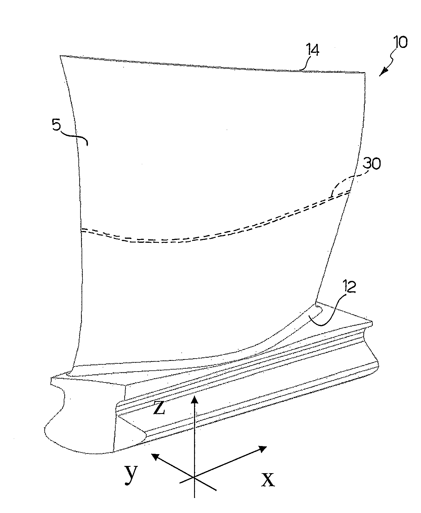
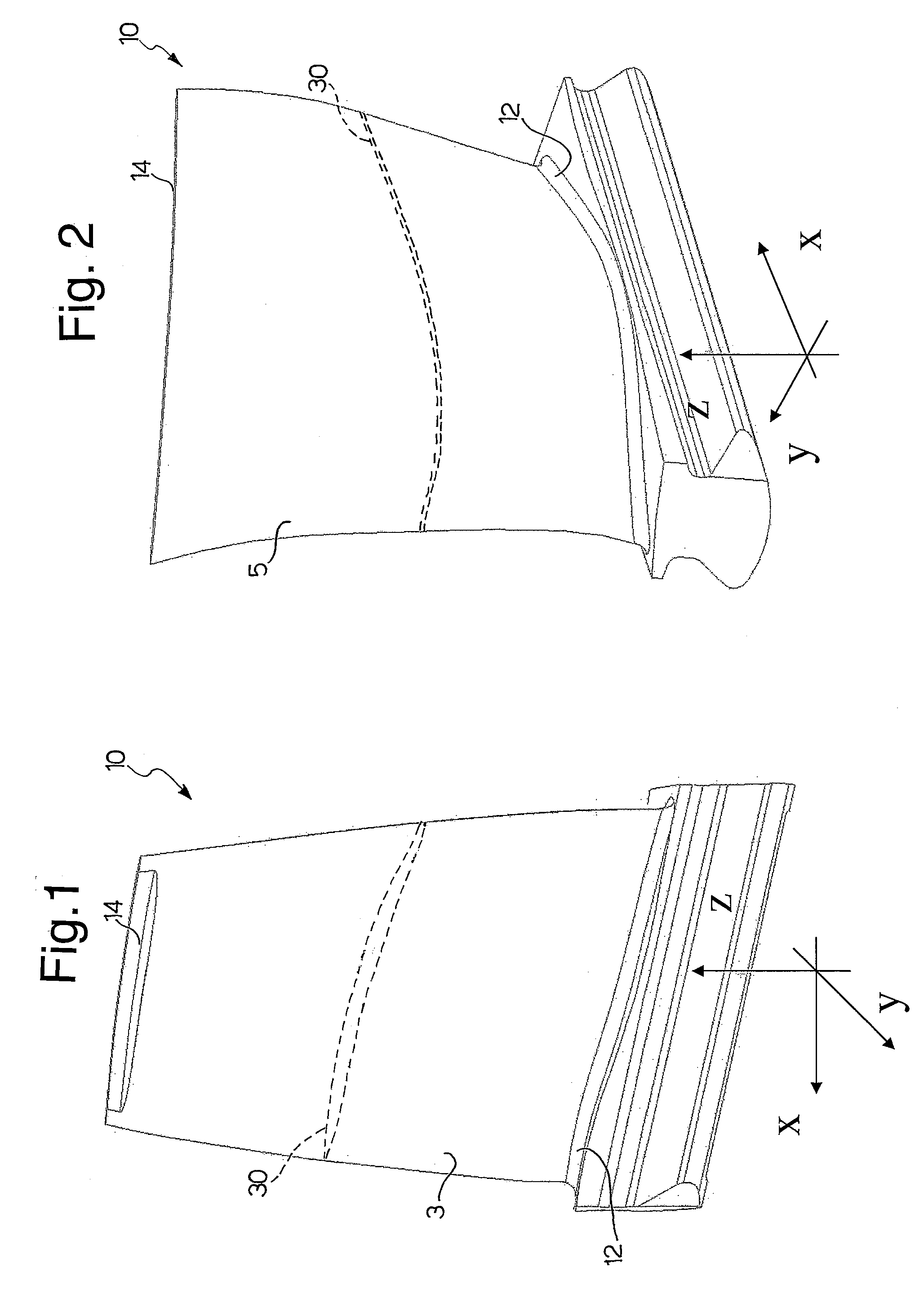
[0022]With reference to the figures, a blade 10 is provided of a rotor of a second phase of a compressor.

[0023]Said blade 10 is defined by means of coordinates of a discreet combination of points, in a Cartesian reference system (X,Y,Z), wherein the axis (Z) is a radial axis intersecting the central axis of the compressor, not shown.

[0024]The profile of the blade 10 is identified by means of a series of closed intersection curves between the profile itself and planes (X,Y) lying at distances (Z) from the central axis.

[0025]The profile of said blade 10 comprises a first substantially concave surface 3, which is pressurized, and a second substantially convex surface 5 which is in depression and opposite the first.

[0026]The two surfaces 3, 5 are continuous and joined to each other, and together form the profile of said blade 10.

[0027]At a base portion 12, commonly called “foot” of the blade 10, according to the known art there is a connecting joint with the aerodynamic profile of the b...


PUM


Abstract

The invention relates to a blade (10) of a rotor of a second phase of a compressor, which can be defined by coordinates of a discreet combination of points, in a Cartesian reference system (X, Y, Z), wherein the axis (Z) is a radial axis intersecting the central axis of the compressor, said blade (10) having a profile which can be identified by means of a series of closed intersection curves between the profile itself and planes (X, Y) lying at distances (Z) from the central axis, said blade (10) also comprising a thickening (30), substantially parallel to a base portion (12) of the blade (10) itself, fixable to said rotor, said thickening (30) being substantially situated midway up the blade (10) and being suitable for shifting the natural resonance frequencies of the blade (10) itself outside a functioning velocity range of said rotor.

Description

BACKGROUND[0001]1. Field of the Invention[0002]The field of the present invention relates to a blade of a rotor of a second phase of a compressor.[0003]More specifically, the invention relates to a blade of a rotor having a high aerodynamic efficiency of a second phase of a compressor.RELATED ART[0004]Compressors normally pressurize in their interior air removed from the outside.[0005]The fluid penetrates the compressor through a series of inlet ducts.[0006]In these channels, the gas has low pressure and low temperature characteristics, whereas as it passes through the compressor, the gas is compressed and its temperature increases.[0007]In order to increase the efficiency, the compressor is normally divided into various phases, each of which has a rotor and a stator respectively equipped with a series of blades.[0008]In recent years, technologically advanced compressors have been further improved, obtaining an increased improvement in efficiency, operating in particular on the aero...

Claims


Application Information

Patent Timeline
Patent Type & Authority Applications(United States)
IPC IPC(8): B64C27/46
CPCF01D5/141F01D5/288F04D29/324Y10S416/50F05D2250/74F05D2260/96F04D29/668F04D29/32F04D29/38
Inventor NOVORI, ALESSIOARINCI, PAOLOLORUSSO, SALVATORE
Owner NUOVO PIGNONE TECH SRL
Why Eureka
Try Eureka