Apparatus and method for acoustic monitoring of steam quality and flow

a technology of acoustic monitoring and steam, applied in the direction of instruments, liquid/fluent solid measurement, fluid analysis using sonic/ultrasonic/infrasonic waves, etc., can solve the problem that the ultimate recovery rate of conventional production is often below 10%, and the cost of generating steam is high

Active Publication Date: 2016-09-13
TRIAD NAT SECURITY LLC
View PDF12 Cites 5 Cited by
  • Summary
  • Abstract
  • Description
  • Claims
  • Application Information

AI Technical Summary

Benefits of technology

[0021]Benefits and advantages of embodiments of the present invention include, but are not limited to, providing an apparatus and method for noninvasively monitoring steam quality and flow rate of steam flowing in a pipe from acoustic measurements made in direct contact with the pipe or remotely thereto. At certain frequencies, such acoustic measurements may be made through pipe insulation.

Problems solved by technology

Conventional production practices cannot recover a large percentage of this oil partly because high viscosity at reservoir conditions inhibits flow to production wells.
Therefore, ultimate recovery by conventional production is frequently below 10%.
However, the cost for generating steam is high, accounting for about one-half of all steam-flooding operating costs.
Because of the high steam cost and the difficulty in obtaining generator permits, optimization of the use of injected steam is necessary.
However, the quality or steam delivered to the reservoir is largely unknown, which makes steam quality measurements important for both oil extraction and reservoir management.
However, this method produces unnecessary noise and releases steam into the environment.
Since these approaches require either penetration of the steam-carrying pipes or insertion of devices into the pipe, none provides a simple and noninvasive method for monitoring steam quality that can be installed at one location and then readily moved to another location without significant plumbing changes, often rendering these methods unsuitable for field use.

Method used


Image

  • Apparatus and method for acoustic monitoring of steam quality and flow
  • Apparatus and method for acoustic monitoring of steam quality and flow
  • Apparatus and method for acoustic monitoring of steam quality and flow

Examples


Embodiment Construction

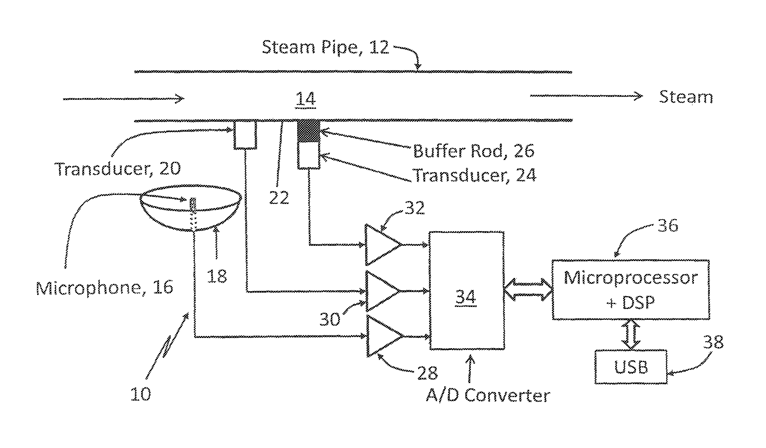
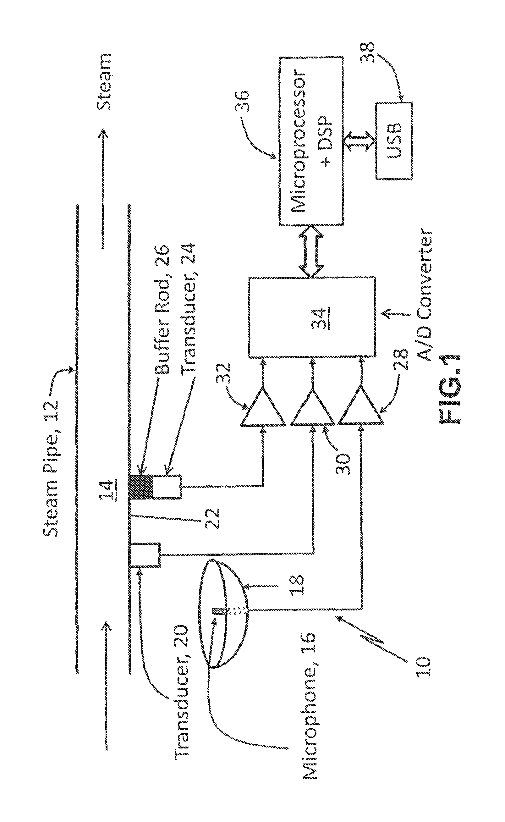
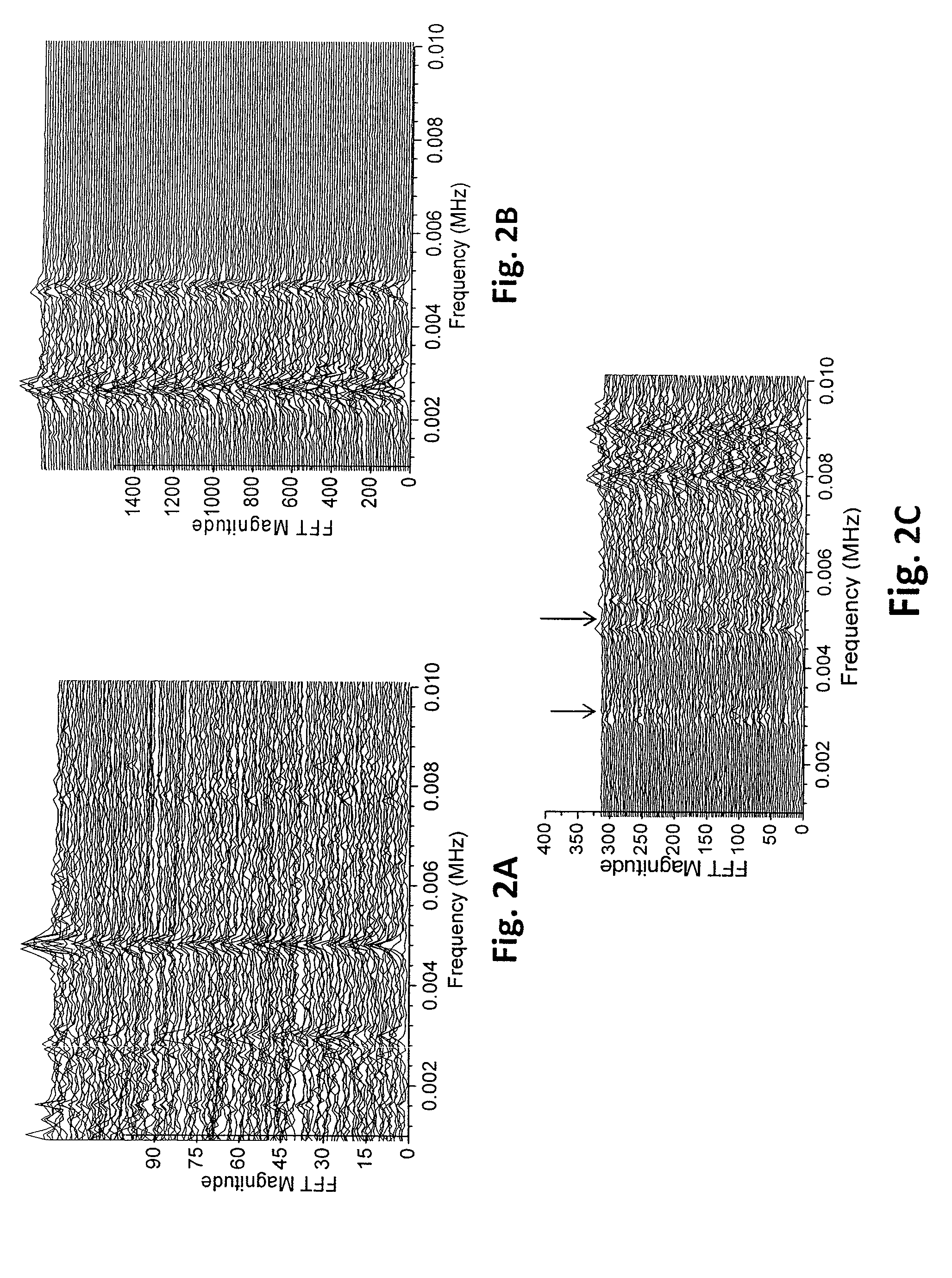
[0027]When steam and, in particular wet steam, flows through a pipe, flow-induced vibrations are generated in the pipe at frequencies which range between the low audible to above normal hearing. As the steam quality changes, the generated frequency spectrum in the pipe varies with it. Embodiments of the present invention include an apparatus and method for noninvasively monitoring steam quality and flow in pipes and conduits bearing flowing steam. Measuring acoustic vibrations generated in steam-carrying conduits by the flowing steam either by direct contact with the pipe or remotely thereto, converting the measured acoustic vibrations into a frequency spectrum characteristic of the natural resonance vibrations of the pipe, and monitoring the amplitude and / or the resonance frequency of one or more chosen resonance peaks, permits changes in the flow rate of the steam in the pipe to be determined.

[0028]The steam quality and the steam flow rate are inversely related, as will be discuss...


PUM

PropertyMeasurementUnit
temperaturesaaaaaaaaaa
stand-off distanceaaaaaaaaaa
diameteraaaaaaaaaa

Abstract

An apparatus and method for noninvasively monitoring steam quality and flow and in pipes or conduits bearing flowing steam, are described. By measuring the acoustic vibrations generated in steam-carrying conduits by the flowing steam either by direct contact with the pipe or remotely thereto, converting the measured acoustic vibrations into a frequency spectrum characteristic of the natural resonance vibrations of the pipe, and monitoring the amplitude and / or the frequency of one or more chosen resonance frequencies, changes in the steam quality in the pipe are determined. The steam flow rate and the steam quality are inversely related, and changes in the steam flow rate are calculated from changes in the steam quality once suitable calibration curves are obtained.

Description

CROSS-REFERENCE TO RELATED APPLICATIONS[0001]The present application claims the benefit of U.S. Provisional Patent Application No. 61 / 449,791 for “Method And Apparatus For Acoustic Steam Quality Monitoring” which was filed on Mar. 7, 2011, the entire contents of which is hereby specifically incorporated by reference herein for all that it discloses and teaches.STATEMENT REGARDING FEDERAL RIGHTS[0002]This invention was made with government support under Contract No. DE-AC52-06NA25396 awarded by the U.S. Department of Energy. The government has certain rights in the invention.FIELD OF THE INVENTION[0003]The present invention relates generally to oil recovery using steam and, more particularly to the noninvasive, real-time measurement of steam quality and flow.BACKGROUND OF THE INVENTION[0004]Heavy oil represents a substantial fraction of world petroleum reserves. Conventional production practices cannot recover a large percentage of this oil partly because high viscosity at reservoir ...

Claims


Application Information

Patent Timeline
Patent Type & Authority Patents(United States)
IPC IPC(8): G01F1/66G01N29/036G01N29/36
CPCG01N29/036G01F1/666G01F1/66G01N29/02
Inventor SINHA, DIPEN N.PANTEA, CRISTIAN
Owner TRIAD NAT SECURITY LLC
Why Eureka
Try Eureka