Magnetic coupling resonant radio energy transmission structure based on passive LC resonance coil

A resonant radio and resonant coil technology, applied in the direction of circuit devices, electrical components, etc., can solve problems such as the inability to realize large-angle power transmission, and achieve the expansion of transmission distance and angle, expansion of distance and angle, transmission angle and transmission distance. Effect

Pending Publication Date: 2019-09-06
JIANGSU UNIV OF TECH
View PDF0 Cites 5 Cited by
  • Summary
  • Abstract
  • Description
  • Claims
  • Application Information

AI Technical Summary

Problems solved by technology

[0006] In order to solve the shortcomings of the magnetic coupling resonant wireless power transmission technology, the transmission efficiency is inversely proportional to the transmission distance, an...

Method used


Image

  • Magnetic coupling resonant radio energy transmission structure based on passive LC resonance coil
  • Magnetic coupling resonant radio energy transmission structure based on passive LC resonance coil
  • Magnetic coupling resonant radio energy transmission structure based on passive LC resonance coil

Examples


Embodiment 1

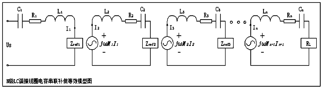
[0044] The present invention lists the Kirchhoff equation through the mutual inductance model of the multi-level resonant coil, thereby obtaining the current at all levels and the reflected impedance at all levels, that is, the current formula of the resonant coil at all levels is as follows:

[0045]

[0046] Without taking into account the mutual inductance that exists between non-adjacent LC resonant coils, and Then the following is the size of the equivalent impedance of each level of reflection:

[0047]

[0048] in Then, according to the current and reflection impedance formulas of the LC resonant structures at all levels calculated according to the above formula, the output power is obtained as:

[0049] P 0 =|I n | 2 R L =f 1 (k 1 ,k 2 ,...,k n-1 , R 1 , R 2 ,...,R n , R L ) (1)

[0050] The function of system efficiency can also be obtained:

[0051]

[0052] When resonance occurs, Then for the resonant system, each stage of the LC resonant s...

Embodiment 2

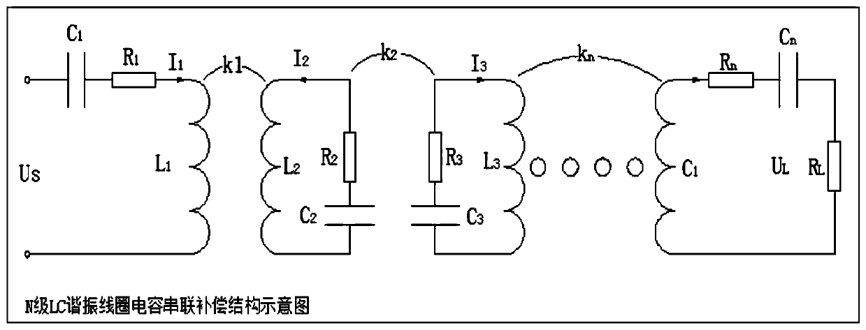
[0071] The present invention first uses a capacitor series (SS) compensation resonance structure, and then adds two LC resonance coils on this structure, so that the whole structure becomes a four-resonance coil magnetically coupled wireless power transmission. The function is to enable the transmission distance of wireless energy to be expanded. like figure 1 As shown, the first resonant tank consists of L 1 , C 1 , R 1 Composed of, the second resonant tank consists of L 2 , C 2 , R 2 composition, the third resonant tank is formed by L 3 , C 3 , R 3 constituted, the fourth resonant tank is passed through L 4 , C 4 , R 4 , R L made up of.

[0072] Then the reflection impedance corresponding to the fourth resonant circuit being equivalent to the third resonant circuit is:

[0073]

[0074] The reflection impedance of the third resonant circuit equivalent to the second resonant circuit is:

[0075]

[0076] The reflection impedance of the second resonant cir...


PUM


Abstract

The invention discloses a magnetic coupling resonant radio energy transmission structure based on a passive LC resonance coil. Multiple stages of resonance coils are introduced between a sending coiland a load coil, that is, a capacitor series compensating resonance structure, wherein the first stage of sending coil is connected to a high-frequency power supply; the introduced second stage of resonance coil serves as a source coil to receive and store the energy transmitted from the sending coil, and transmits the energy to the next stage; and the introduced (n-1)th stage of resonance coil serves as a driving coil to receive the energy transmitted from the previous stage, and meanwhile, is connected to the load for load consumption, and transmits the last stage of load coil. The same resonance coils are introduced to connect with the capacitor to form an LC resonance structure, the natural resonance frequency of which is same with the driving end excitation frequency. Through coupling units for radio energy transmission, radio energy transmission distance and angle are greatly improved while good transmission efficiency is ensured.

Description

technical field [0001] The invention relates to the field of wireless power transmission, in particular to a magnetic coupling resonant wireless power transmission structure based on a passive LC resonant coil. Background technique [0002] In modern society, people's life is inseparable from electric energy, and with the development of science and technology, the development of high-precision electronic products makes people have higher and higher requirements for electric energy transmission in daily life and industrial production. For now, with the extensive use of traditional wired power supply methods in power transmission, its problems in safety and other aspects have become more and more prominent as time goes by. It is mainly reflected in the fact that the wire takes up a large space when the wire is used for connection. At the same time, if the wire is not tightly wound and connected, it will cause electromagnetic interference, and if it is serious, it will cause a ...

Claims


Application Information

Patent Timeline
IPC IPC(8): H02J50/12H02J50/70
CPCH02J50/12H02J50/70
Inventor 刘晓杰刘超张旻贾子彦张婧婕薛波罗印升吴全玉宋伟俞洋崔渊
Owner JIANGSU UNIV OF TECH
Why Eureka
Try Eureka