Inclination sensor

Active Publication Date: 2008-02-28
ASM AUTOMATION SENSORIK MESSTECHN GMBH
View PDF9 Cites 15 Cited by
  • Summary
  • Abstract
  • Description
  • Claims
  • Application Information

AI Technical Summary

Benefits of technology

[0017] It is an object of the present invention to provide an inclination sensor which is simpl

Problems solved by technology

The mechanically more simple configuration of a float housed in a fluid compared to a mechanically exact support, is traded off against the disadvantage that thus the pivot axis of the float can be held less exact than thro

Method used


Image

  • Inclination sensor
  • Inclination sensor
  • Inclination sensor

Examples


Embodiment Construction

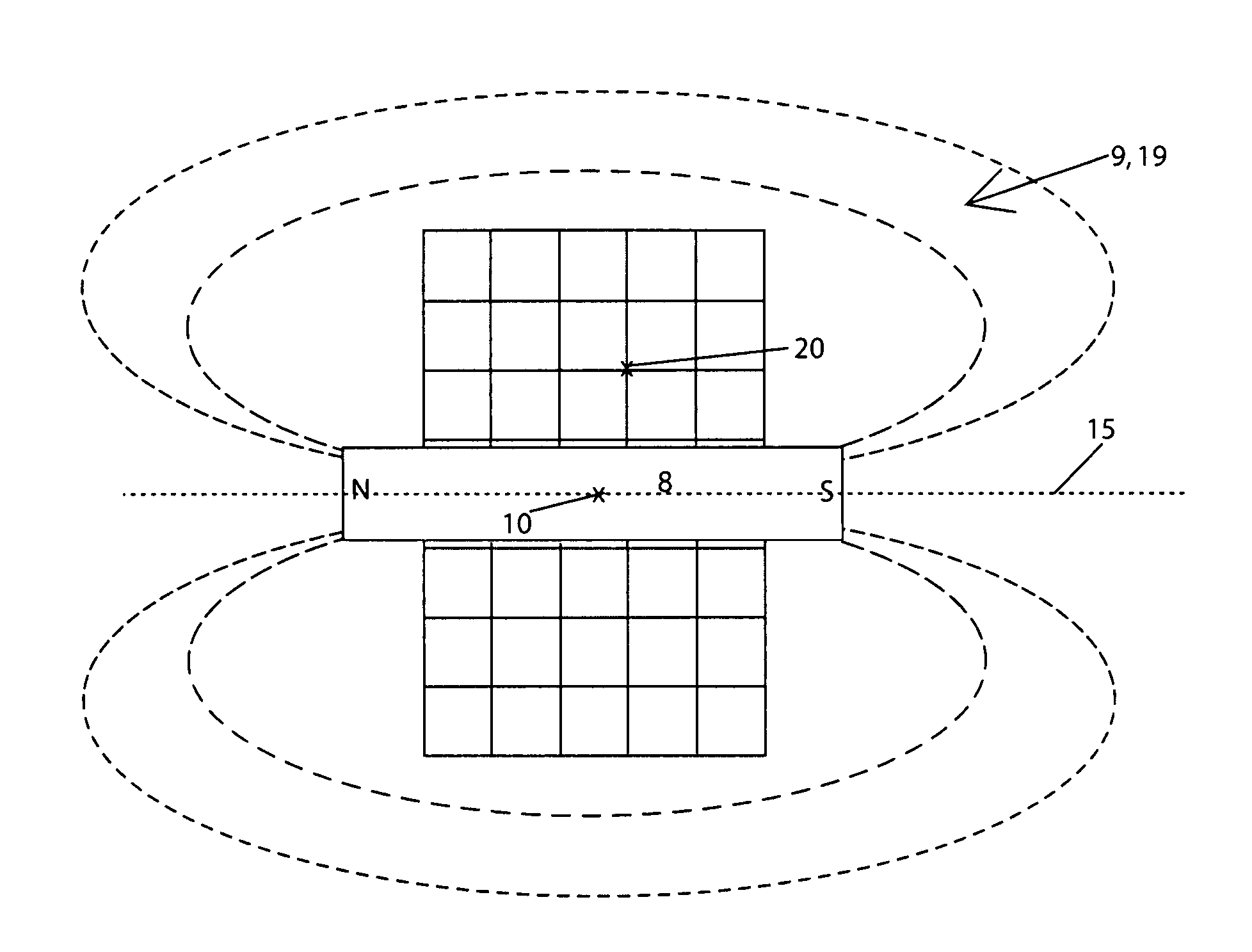
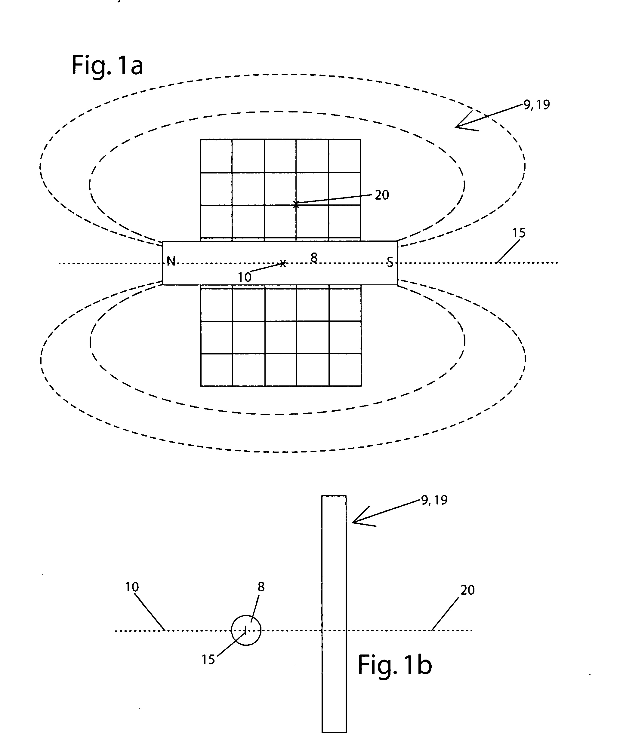
[0065]FIGS. 1a-b show a basic configuration used for an inclination sensor 1: a flat magnetosensitive sensor 9 capable of measuring a static gradient of a magnetic field, e.g. a multi-Hall-chip 19, is disposed relative to an indicator magnet 8, e.g. a permanent magnet, with a pair of poles, so that its pole axis 15 extends in parallel in front of the sensor 9, 19.

[0066] Through pivoting an indicator magnet 8, thus pole axis 15, relative to the perpendicular of the surface of sensors 9, 19, thus around a neutral magnet axis 20 or an approximately parallel pivot axis 10, sensor 9 determines the tilt, e.g. through the multi-Hall-IC 19 relating the differences of the magnetic flux densities of the particular surface areas of the IC relative to each other.

[0067] In comparison, changes in the distance of pole axis 15 relative to the surface of the sensor, and thus also pivoting motions of pole axis 15 around an axis located parallel to the sensor plane, hardly affect the measurement res...


PUM


Abstract

Inclination sensors with magnetic XMR- or Hall-sensor-principles were implemented in the past by the pivotably supported indicator magnet being supported on the front face of the axle of a pendulum, with the consequence that the static friction of the support had to be overcome first, before the inclination sensor would react. Thereby very small and very slow inclinations often could not be detected. These designs always have a large amount of hysteresis. According to the invention this problem is being solved by the indicator magnet being mounted either on a float, or on a pendulum that is being supported ferrofluidic, whereby the static friction is much smaller or eliminated entirely.

Description

CROSS REFERENCE TO RELATED APPLICATIONS [0001] This application claims priority to German Patent Application No 102006025379.5 filed May 31, 2006 and to German Patent Application No. 102006061198.5 filed Dec. 22, 2006. STATEMENT REGARDING FEDERALLY SPONSORED RESEARCH [0002] Not Applicable INCORPORATION-BY-REFERENCE MATERIAL SUBMITTED ON A COMPACT DISC [0003] Not ApplicableBACKGROUND OF THE INVENTION [0004] 1. Field of the Invention [0005] This invention relates to an inclination sensor [0006] 2. Description of Related Art [0007] There are various designs of inclination sensors. [0008] Previously, mercury was very often used in order to detect the shifting position of the mercury in the inclination sensor. For reasons of environmental concerns, the application of such mercury sensors is no longer legal in most cases. [0009] Thereafter, pendulum sensors are commonly used. In this context, a pendulum always assumes an exactly vertical position corresponding to the current gravitational...

Claims


Application Information

Patent Timeline
IPC IPC(8): G01C9/06
CPCG01C9/06G01C9/12G01C2009/187G01C2009/064G01C9/20
Inventor STEINICH, KLAUS MANFRED
Owner ASM AUTOMATION SENSORIK MESSTECHN GMBH
Why Eureka
Try Eureka