Eureka AIR delivers breakthrough ideas for toughest innovation challenges, trusted by R&D personnel around the world.

Sensor for detecting the level of a medium

a technology of a sensor and a level, applied in the direction of electronic switching, pulse technique, instruments, etc., can solve the problems of complex general structure of sensors, aging and early wear of sensors, and achieve the effects of simple and inexpensive production, high flexibility of use and construction

Active Publication Date: 2017-09-14
ELTEK
View PDF7 Cites 13 Cited by
  • Summary
  • Abstract
  • Description
  • Claims
  • Application Information

AI Technical Summary

Benefits of technology

The present invention is designed to provide an easy and inexpensive level sensor that is flexible and durable. The technical effect of this invention is that it can be produced in different lengths without compromising accuracy and reliability.

Problems solved by technology

These sensors are in general complicated from the mechanical standpoint and present some critical aspects, such as risks of jamming.
These sensors are inevitably affected by problems linked to possible freezing of the medium undergoing measurement.
In these known solutions, the electrodes are directly in contact with the liquid and hence subject to aging and to early wear.
Known sensors of this type envisage configurations with a respective impedance, which may even behave as antennas and present the problem of generating electromagnetic interference (EMI), this disturbance being such as to interfere with other electronic systems, such as the electronic circuits on board the vehicle.
In addition to causing problems of encumbrance, a solution of this kind presents limits in the measurement resolution or precision.
This entails the need to use signals in frequency having higher power in order to detect the level of the liquid in the tank, and this determines greater risks for the aforesaid electromagnetic interference.

Method used


Image

  • Sensor for detecting the level of a medium
  • Sensor for detecting the level of a medium
  • Sensor for detecting the level of a medium

Examples


Embodiment Construction

[0041]Reference to “an embodiment” or “one embodiment” in the framework of the present description is meant to indicate that a particular configuration, structure, or characteristic described in relation to the embodiment is comprised in at least one embodiment. Hence, phrases such as “in one embodiment”, “in one embodiment”, and the like that may be present in different points of this description do not necessarily refer to one and the same embodiment, but may instead refer to different embodiments. Moreover, particular conformations, structures, or characteristics defined in the course of the present description may be combined in any adequate way in one or more embodiments, even different from the ones shown. The numeric and spatial references (such as “upper / top”, “lower / bottom”, “up”, “down”, “front”, “back”, “vertical”, etc.) used herein are merely provided for convenience and hence do not define the sphere of protection or the scope of the embodiments. In the figures, the sam...


PUM


Abstract

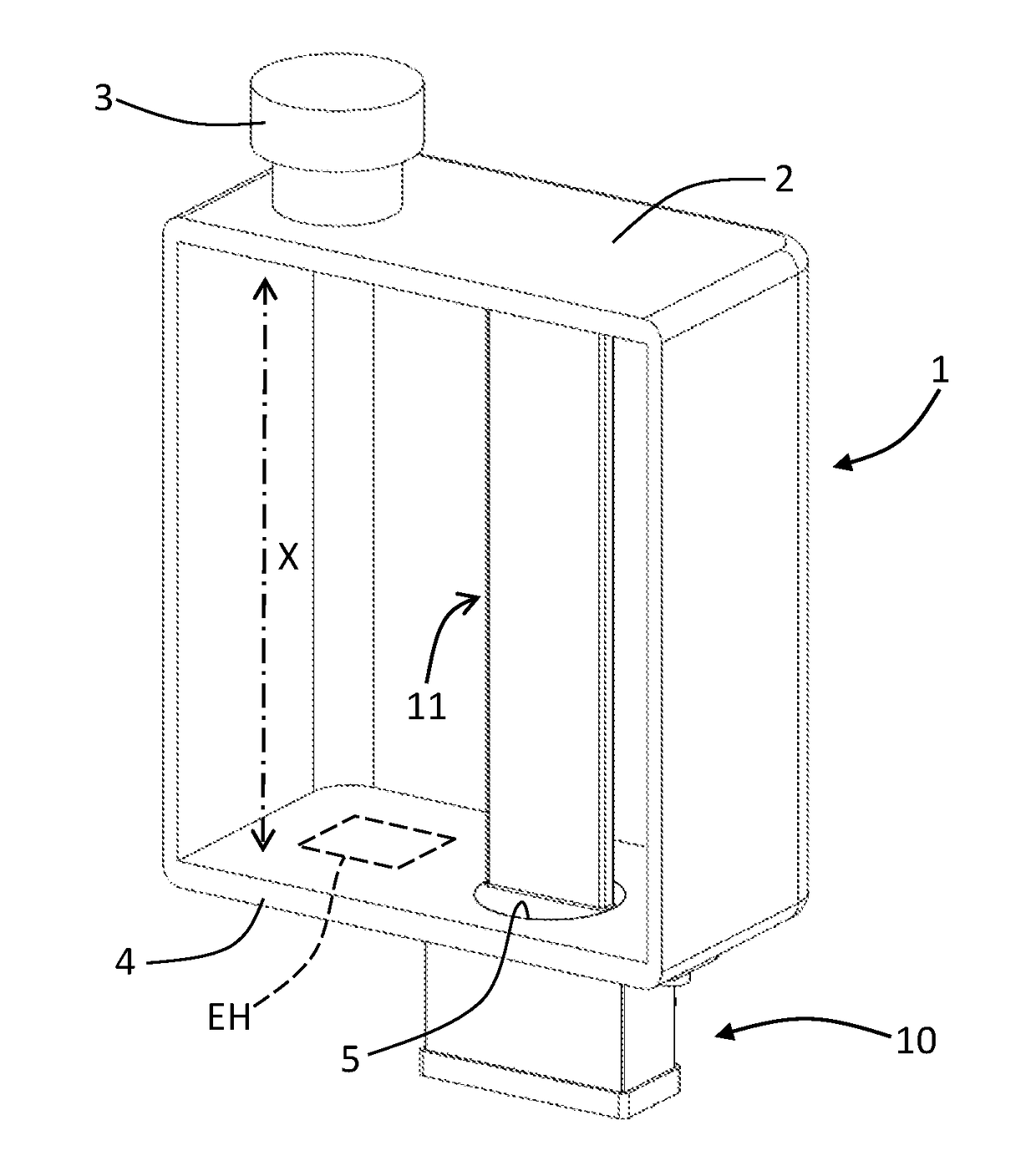
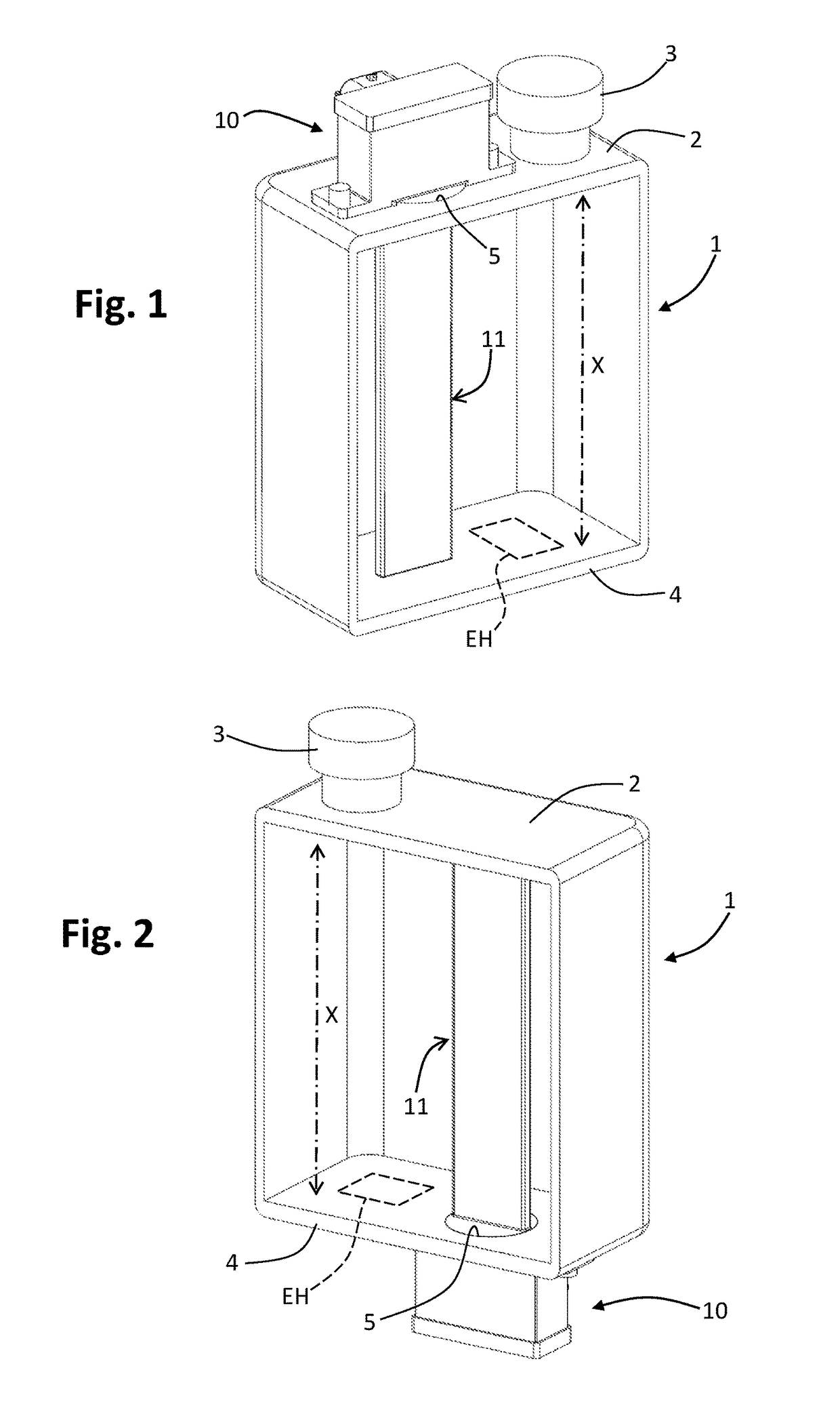
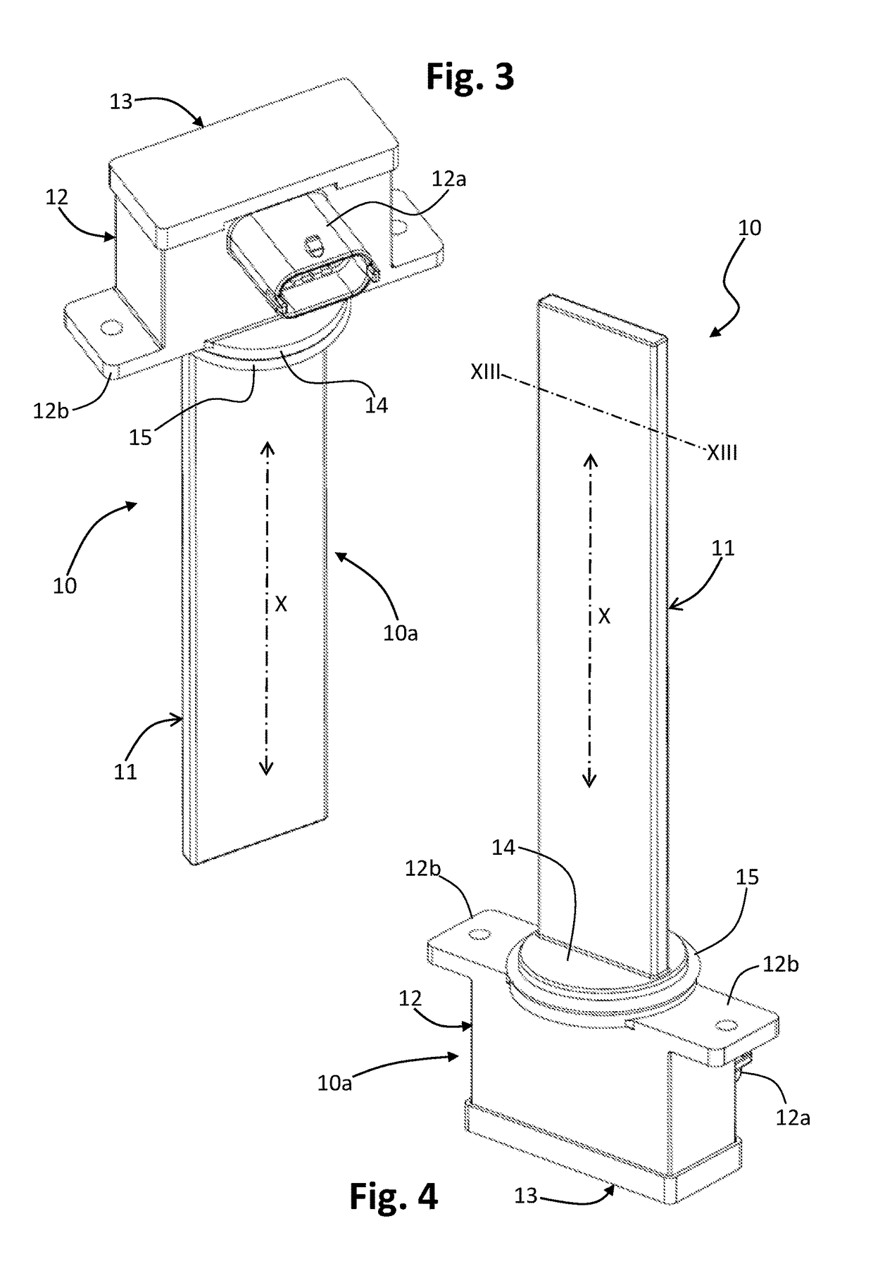
A sensor for detecting the level of a medium contained in a container, in particular a tank, comprises: an array of capacitive elements designed to be associated to the container (1), in particular so as to extend according to an axis of detection (X) of the level of the medium (L), the array of capacitive elements comprising a plurality of electrodes (Ji-Jn), in particular on a face of an electrically insulating substrate (20) having a generally elongated shape, the electrodes (Ji-Jn) being spaced apart from one another, in particular along the detection axis (X), and being preferably substantially coplanar with one another; at least one insulation layer (16) for insulating electrically the electrodes (Ji-Jn) with respect to the inside of the container (1); and a controller (24) having a plurality of inputs. Each capacitive element comprises at least one of a single electrode and a set of electrodes connected together in common, in particular in parallel, the single electrode or the set of electrodes being connected to a respective input of the plurality of inputs. The controller (24) is pre-arranged for discriminating a value of capacitance associated to each electrode (Ji-Jn) in order to deduce the level of the medium present container.

Description

FIELD OF THE INVENTION[0001]The present invention relates to a sensor for detecting the level of a generic medium, such as a liquid, a fluid substance, a powdery material, or a material in the bulk state, etc. The invention has been developed with particular reference to level sensors of a capacitive type used on vehicles.PRIOR ART[0002]Level sensors are used in various contexts for detecting a residual amount of a liquid present in a generic container, such as a tank. Some of these sensors are based upon the use of a float. These sensors are in general complicated from the mechanical standpoint and present some critical aspects, such as risks of jamming. These sensors are inevitably affected by problems linked to possible freezing of the medium undergoing measurement.[0003]Also known are level sensors based upon the measurement of electrical quantities, such as conductivity / resistivity or capacitance. These sensors usually have an array of first electrodes, arranged according to th...

Claims


Application Information

Patent Timeline
Patent Type & Authority Applications(United States)
IPC IPC(8): G01F23/26
CPCG01F23/268G01F23/266G01F23/265G01F23/26G01F23/263H03K17/955H03K2217/960725
Inventor RONDANO, MATTEOCHIESA, ENRICOZORZETTO, MAUROCANTARELLI, DOMENICO
Owner ELTEK
Why Eureka
Eureka Blog
Learn More