Clip Integration of Pressure Tube Mold Cores into Hardened Omega-Stringers for the Production of Stiffened Fiber Composite Skin Shells, in particular for Aeronautics and Astronautics

a fiber composite shell and omega technology, applied in the field of stiffening systems and methods of fiber composite shells, can solve the problems requiring an additional working step, and entail additional weight, and reducing the production efficiency of the fiber composite component. , the effect of reducing the waviness of the fiber composite componen

Active Publication Date: 2010-01-14
AIRBUS OPERATIONS GMBH
View PDF13 Cites 13 Cited by
  • Summary
  • Abstract
  • Description
  • Claims
  • Application Information

AI Technical Summary

Benefits of technology

[0026]The device according to the invention makes it possible to markedly simplify the production of flat components, in particular the production of a fiber composite component, by reducing and simplifying the process steps. The non-defined accumulation of resin used for hardening the fiber composite component, cracking in the fiber composite component due to the provision of rounded-out portions and the waviness of the fiber composite component are markedly reduced. To stiffen the flat component, the device can be connected thereto. That can be effected by means of any suitable connecting procedure, for example by riveting or screwing. Additionally, or alternatively, the device (e.g., a stringer) can be glued in the hardened condition to an outer surface, which has not yet hardened (wet), of a material layer of the fiber composite component, also referred to as the skin, as is used in the present invention. If the device is in the form of a stringer, it can be made from a material which is matched to the material layers of the fiber composite / the skin so that the join between the stringer and the fiber composite / the skin can be particularly easily afforded, for example by adhesive means. The other advantages referred to in relation to the device also apply to the flat component and the fiber composite.
[0027]A further development of the flat component advantageously provides that the mold core is in the form of a pressure tube. The pressure tube can be connected to an internal space of an autoclave so that the pressure generated by the autoclave and the temperature produced by the autoclave can be introduced into the flat component, in particular into the fiber composite component, along the device, in particular along the stringer. It is possible in that way to easily implement uniform hardening and pressing of the material layers of the fiber composite component and uniform integration or connection of the stringer to the material layers. As mentioned hereinbefore in accordance with the invention the operation of introducing the pressure tube into the stringer can be automated. In that way manufacture of the fiber composite component can be simplified and thus made less expensive.
[0028]Preferably a development of the flat component provides that the material layer or layers is or are at least partially constructed from hardenable material such as fiber composite material, in particular carbon fiber or glass fiber reinforced plastic. In that way shell segments can be produced in an inexpensive and simple fashion, which are light and which nonetheless can be subjected to a high loading. In addition there is the possibility of the stringer being joined to the material layers by adhesive means, which is a simpler joining procedure in comparison for example with riveting or screwing.

Problems solved by technology

It will be noted however that there is the disadvantage here that introducing the prepreg requires an additional working step and entails additional weight, both of which are undesirable.
It will be noted however that in that case there is the danger of damage to the pressure tube and the formation of pressure tube folds which are transmitted to the fiber composite component upon integration as between the device and the skin.
Both methods of introducing the pressure tube into the device involve the risk that the pressure tube slips, the pressure tube cannot be positioned exactly in the device and it is not possible to arrive at defined corner radius formation as inaccuracies in positioning of the pressure tube mean that it is fitted snugly into the corner regions of the device to differing extents.

Method used


Image

  • Clip Integration of Pressure Tube Mold Cores into Hardened Omega-Stringers for the Production of Stiffened Fiber Composite Skin Shells, in particular for Aeronautics and Astronautics
  • Clip Integration of Pressure Tube Mold Cores into Hardened Omega-Stringers for the Production of Stiffened Fiber Composite Skin Shells, in particular for Aeronautics and Astronautics
  • Clip Integration of Pressure Tube Mold Cores into Hardened Omega-Stringers for the Production of Stiffened Fiber Composite Skin Shells, in particular for Aeronautics and Astronautics

Examples


first embodiment

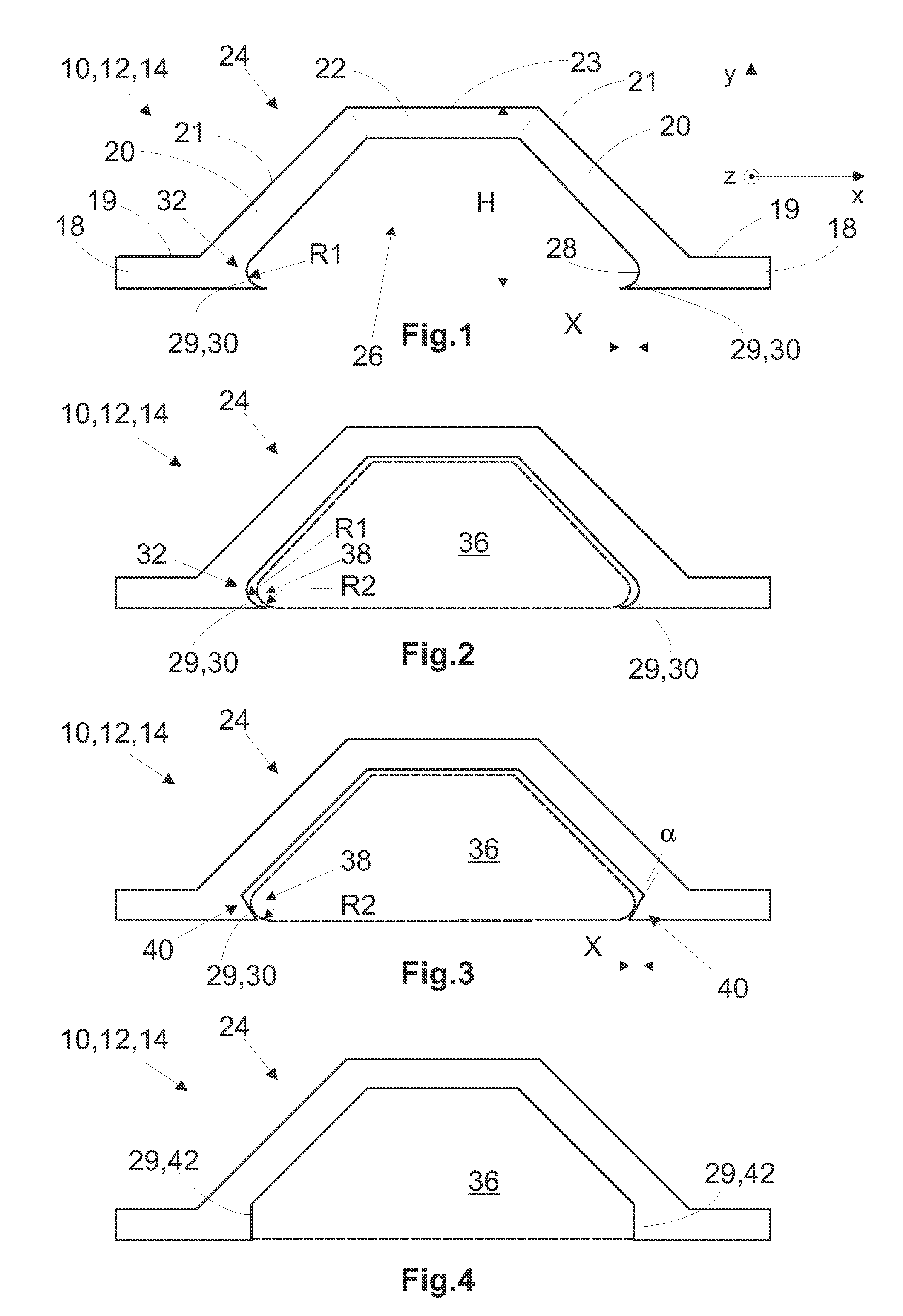
[0057]FIG. 1 shows the device 10 according to the invention which is in the form of an omega-stringer 12 in a first embodiment, in which respect stringers 14 can be used in any other conceivable design configuration, for example a T-stringer. The omega-stringer 12 includes a wall 16 having respective first, second and third wall portions 18, 20, 22 with a first, a second and a third surface 19, 21 and 23. The wall portions 18, 20 and 22 respectively go into each other. The first and third surfaces 19 and 23 of the first and third wall portions 18 and 22 extend substantially along an x-axis in a co-ordinate system defined in FIG. 1. The second surface 21 of the second wall portion 20 extends at a freely selectable angle to the first and third surfaces 19 and 23 respectively. The individual wall portions 18, 20 and 22 can be of any desired dimensions. The height H, produced thereby, of the omega-stringer 12 can be 30 mm. On the one hand that provides for stiffening of a later fiber co...

second embodiment

[0059]FIG. 3 shows the device according to the invention in the form of the omega-stringer 12. In this case the projections 30 are in the form of a slope 40, wherein an angle α included by the slope 40 with the vertical can be selected as desired as long as it is ensured that the mold core 36 is securely positioned in the space 26. The angle α can assume in particular values in the region of −5° to +450.

[0060]In addition the slopes 40 can also be of any desired dimensions. In this embodiment the mold core 36 is of precisely the same shape as in FIG. 2, but it is apparent that the mold core 36 can be so shaped as to be adapted to the slopes 40 of the projections 30. The undercut configuration X produced by the projections 30, that is to say the extent of the projections 30 in the x-direction, can be selected to be as desired, irrespective of its configuration, and can be for example 2 mm. Slightly negative values are also conceivable, as long as it is possible to guarantee a sufficie...

third embodiment

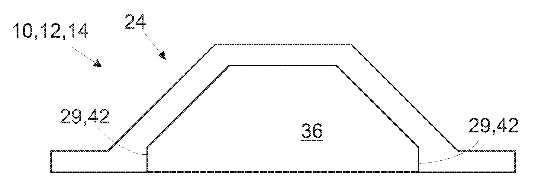
[0061]FIG. 4 shows the omega-stringer 12 in a In this case it does not have any projections. The mold core 36 is positioned in the space 26 by way of surfaces 42 which are of such a configuration that they exert a clamping action on the mold core 36 so that the mold core 36 is held in the space 26. In addition in this example the mold core 36 completely fills up the space 26 and is therefore of a shape corresponding to that of the space 26. That prevents the mold core 36 from being able to move in the space 26. When the mold core 36 is completely introduced into the space 26 consequently its position is uniquely fixed. Otherwise the omega-stringer is identical to the structure shown in FIGS. 1 and 2.

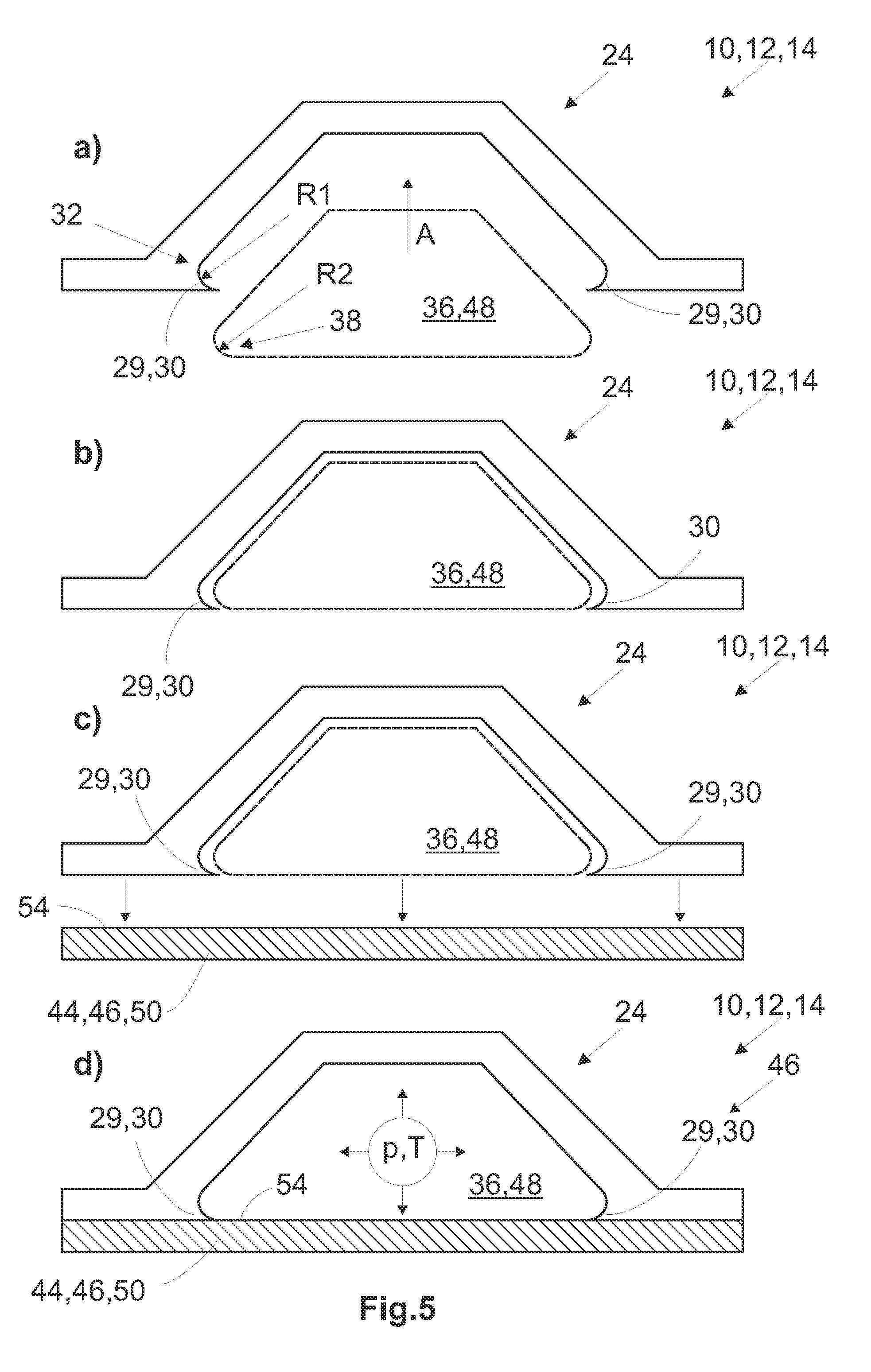
[0062]FIGS. 5a) through 5d) show the essential steps in a process according to the invention for the production of a flat component 44, in particular a fiber composite component 46. The illustrated example uses the omega-stringer 12 shown in FIGS. 1 and 2. The mold core 36 used is a dim...


PUM

PropertyMeasurementUnit
pressuresaaaaaaaaaa
heightaaaaaaaaaa
radius R1aaaaaaaaaa

Abstract

The invention concerns a device for stiffening a flat component, a process for the production of a flat component, in particular a fiber composite component, and a fiber composite component. The device has a portion for producing a space for receiving a mold core for the transmission of a pressure for pressing the flat component and the device. It is characterised by means for positively lockingly and/or frictionally lockingly positioning the mold core in the space of the device. The process according to the invention includes the following steps: introducing the mold core into the portion of the device, positively lockingly and/or frictionally lockingly positioning the mold core in the portion of the device by means of the means, applying the device including the mold core to the non-hardened material layer or layers, pressing the material layers, and hardening the material layer or layers and joining the device to the material layer or layers.

Description

PRIORITY[0001]The present application claims priority from the U.S. Provisional Application 61 / 080,433, filed Jul. 14, 2008, and DE 10 2008 032 834.0, also filed Jul. 14, 2008, both of which are hereby incorporated by reference in their entireties.FIELD OF THE INVENTION[0002]The invention generally relates to the production of fiber composite components and, more particularly, the invention relates to systems and methods for stiffening fiber composite shells.BACKGROUND OF THE INVENTION[0003]It is generally known for flat components to be produced in the form of fiber composite components comprising one or more layers for example of carbon fiber reinforced plastic (CFRP). Those fiber composite components are stiffened with stringers of carbon fiber reinforced plastic in order to withstand the loadings which occur in the aircraft structure, with the lowest possible additional weight. In that respect a distinction is essentially drawn between two kinds of stringers: the T-stringer and ...

Claims


Application Information

Patent Timeline
Patent Type & Authority Applications(United States)
IPC IPC(8): B29C59/02
CPCB29C35/0227Y10T428/24281B29C66/131B29C66/634B29C66/721B29C70/44B29K2105/06B29K2307/00B29K2309/08B29L2009/00B29L2031/307B29L2031/3082B63B5/24B64C1/064B64C3/182B64C2001/0072Y02T50/433Y10T428/1362Y10T428/24273Y10T428/24289Y10T428/24339Y10T428/24322B29C66/112B29C66/71B29C66/7212B29C66/72141B29C66/723B29C66/73161Y02T50/40Y10T428/249994B29K2063/00B29K2307/04
Inventor JACOB, TORBENWIIK, IVAR
Owner AIRBUS OPERATIONS GMBH
Why Eureka
Try Eureka