Rollover car wash for large vehicles

Active Publication Date: 2008-02-28
PISTON OPW INC
View PDF5 Cites 6 Cited by
  • Summary
  • Abstract
  • Description
  • Claims
  • Application Information

AI Technical Summary

Benefits of technology

[0028] According to a further feature of the invention, the wash system further includes a second arm, pivotally mounted on the carriage and including a pivot structure at its inboard end and a spray device mounted on the second arm and the second arm includes a bearing structure including an upper bearing mounted on the carriage frame structure and journaling an upper portion of the pivot structure of the second arm and a lower bearing mounted on the support plate and journaling a lower portion of the pivot structure of the second arm. This arrangement allows the upper and lower bearing structure to accommodate the pivot structure of both arms of a butterfly type washer.
[0029] The invention further provides an arrangement to facilitate the washing of large vehicles hav

Problems solved by technology

Whereas this particular form of rollover car wash is effective in washing relatively small vehicles such as automobiles and small trucks, problems arise when this form of rollover washer is applied to the washing of large vehicles such as large buses and large trucks.
Specifically, because of the necessarily long length of the washer commensurate with the long length of the vehicles being washed, problems arise in maintaining the washing water at a desirable hot temperature as the carriage carrying the spray arms moves to a position remote from the hot water source.
Further, because the washer requires an excessively long track structure to allow the carriage to traverse the entire length of the large vehicles, problems arise with respect to physically construc

Method used


Image

  • Rollover car wash for large vehicles
  • Rollover car wash for large vehicles
  • Rollover car wash for large vehicles

Examples


Example

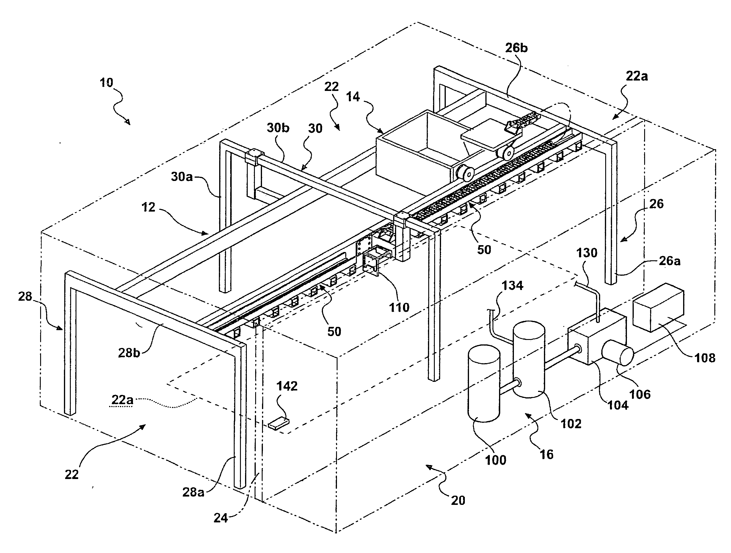
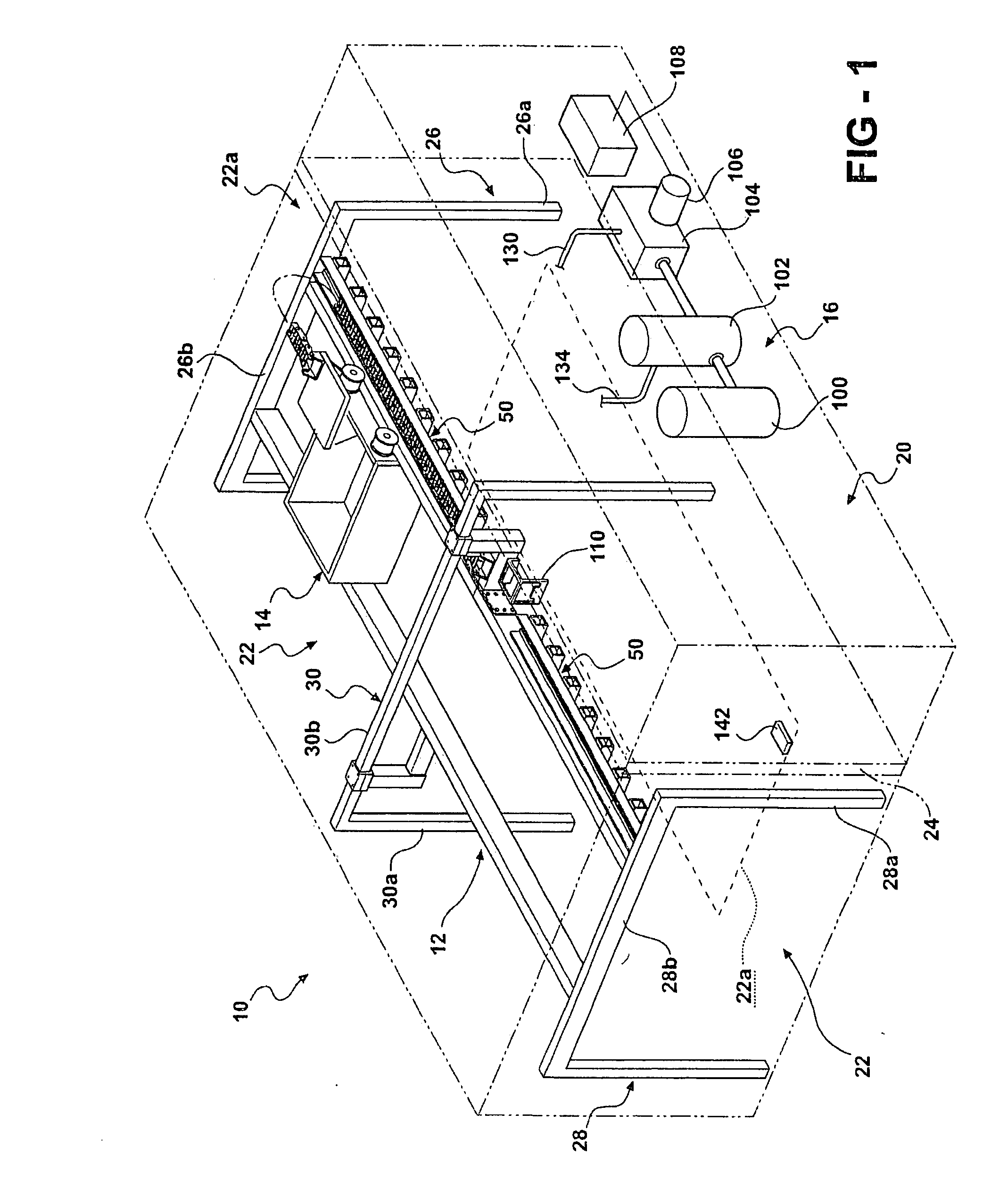
[0044] The rollover washer of the invention is typically installed in a building structure 10 and, broadly considered, includes a frame structure 12, a carriage assembly 14, an equipment room assembly 16, and a supply assembly 18.

[0045] Building structure 10 (FIG. 1) typically includes an equipment room 20 and a wash bay22 positioned parallel to the equipment room and separated from the equipment room by a partition wall 24. The wash bay 22, may for example, have a length between 45′ and 75′ whereby to accommodate even very large vehicles such as eighteen wheel tractor-trailer type trucks.

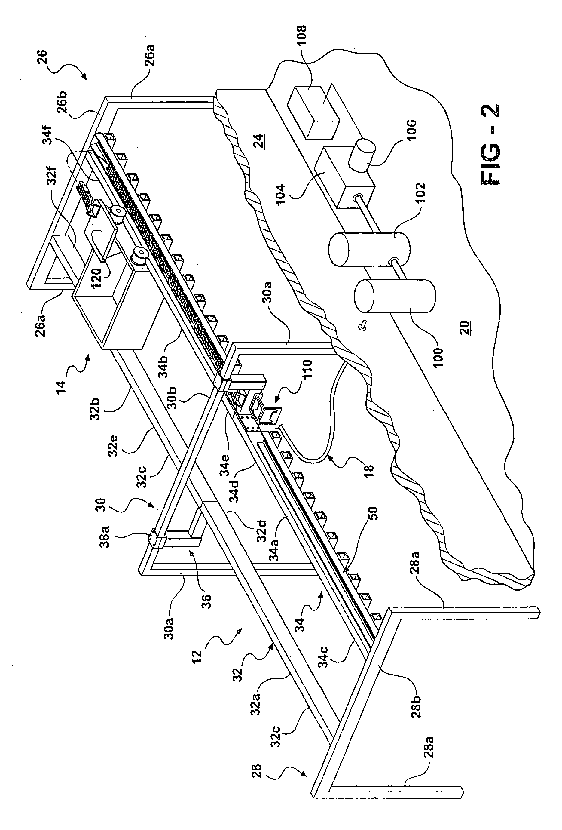
[0046] Frame structure 12 (FIGS. 2, 3 and 12) is of the gantry type and includes an entry gantry 26, an exit gantry 28, and a center gantry 30.

[0047] Entry gantry 26 includes a pair of laterally spaced vertical post members 26a upstanding from the floor surface of the wash area and an upper cross member 26b interconnecting upper ends of the vertical post members.

[0048] Exit gantry 28 includes a...


PUM

PropertyMeasurementUnit
Temperatureaaaaaaaaaa
Speedaaaaaaaaaa
Areaaaaaaaaaaa

Abstract

A vehicle washer of the rollover type especially suitable for washing large vehicles such as buses and trucks. The washer includes an overhead carriage moving along an overhead guide rail structure and including opposed L-shaped spray arms adapted to wash top and side surfaces of the vehicle as the carriage moves along the guide rail and move in butterfly fashion as the carriage reaches a respective end of the vehicle whereby to wash that end of the vehicle. A recirculating arrangement insures that the hot water arriving at the carriage from the equipment room is at a predetermined hot temperature; a flexible carrier folds and unfolds in a trough along the rail structure and threadably receives the various supply conduits to provide effective transport of the required wash elements to the carriage; a compound bearing structure on the carriage efficiently journals the pivotal ends of the very large and heavy spray arms required to process large vehicles; a unique splicing arrangement allows the provision of a long guide rail structure having an uninterrupted upper surface to allow smooth carriage movements; and a customized windshield washer assembly on the carriage allows effective washing of even the recessed windshields of large vehicles having long hoods.

Description

RELATED APPLICATION [0001] This application is a divisional of U.S. application Ser. No. 10 / 828,088 filed under attorney docket no. BGR-135-A on Apr. 20, 2004, currently pending. The content of the U.S. patent Ser. No. 11 / 273,142 is incorporated herein by reference.FIELD OF THE INVENTION [0002] This invention relates to car wash apparatuses, more particularly to car wash apparatuses of the rollover type, and yet more particularly to rollover car wash apparatuses especially suitable for use in washing large vehicles such as buses and trucks. BACKGROUND OF THE INVENTION [0003] Car wash apparatuses are in common usage throughout the world for wet washing the exterior surfaces of various forms of automotive vehicles. [0004] One of the most popular forms of car wash apparatus is the so called “rollover” washer which is characterized by a washing structure which moves over or around a vehicle parked in a pre-specified wash area. [0005] In one particularly effective form of rollover car wa...

Claims


Application Information

Patent Timeline
IPC IPC(8): E03B1/00B08B3/04
CPCB60S3/04
Inventor BELANGER, MICHAEL J.WEYANDT, TOM E.PRATER, CURTIS S.TOGNETI, DAVID L.
Owner PISTON OPW INC
Why Eureka
Try Eureka