Uncoupled vibrion attenuation/isolation devices

a technology of vibration attenuation and isolation device, which is applied in the direction of shock absorbers, cosmonautic vehicles, transportation and packaging, etc., can solve the problems of almost impossible to reach the limit value of longitudinal and lateral link stiffness simultaneously, and the longitudinal stiffness can reach its limit, so as to reduce the bending stiffness of the connection

Inactive Publication Date: 2008-02-28
ZHENG GANGTIE +3
View PDF18 Cites 12 Cited by
  • Summary
  • Abstract
  • Description
  • Claims
  • Application Information

AI Technical Summary

Benefits of technology

[0024]One embodiment of the present invention, referred to as an Uncoupled Whole-Spacecraft Vibration Attenuation / Isolation Device (UWSVA / I), provides a new concept for controlling vibrations in a SC-LV assembly. The UWSVA / I abandons the conventional idea that the longitudinal and lateral vibration loads transmit along the same path to the bottom of the spacecraft. By adopting the independent longitudinal and lateral vibration attenuation / isolation portions, the vibration load is decomposed or resolved into the longitudinal and lateral components, and these components transmit to the spacecraft separately along different paths. Therefore, they can not only meet different requirements of the longitudinal and lateral vibration attenuation / isolation, but also does not decrease the bending stiffness of the connection between the launch vehicle and the spacecraft.

Problems solved by technology

Therefore, they can not only meet different requirements of the longitudinal and lateral vibration attenuation / isolation, but also does not decrease the bending stiffness of the connection between the launch vehicle and the spacecraft.
The longitudinal link stiffness and the lateral link stiffness of traditional PAF devices are coupled together, so it is nearly impossible for the longitudinal and lateral link stiffnesses to reach their limit values simultaneously.
For most cases, the longitudinal stiffness can reach its limit only when lateral stiffness is reduced to an extent that may be unacceptable.

Method used


Image

  • Uncoupled vibrion attenuation/isolation devices
  • Uncoupled vibrion attenuation/isolation devices
  • Uncoupled vibrion attenuation/isolation devices

Examples


example 1

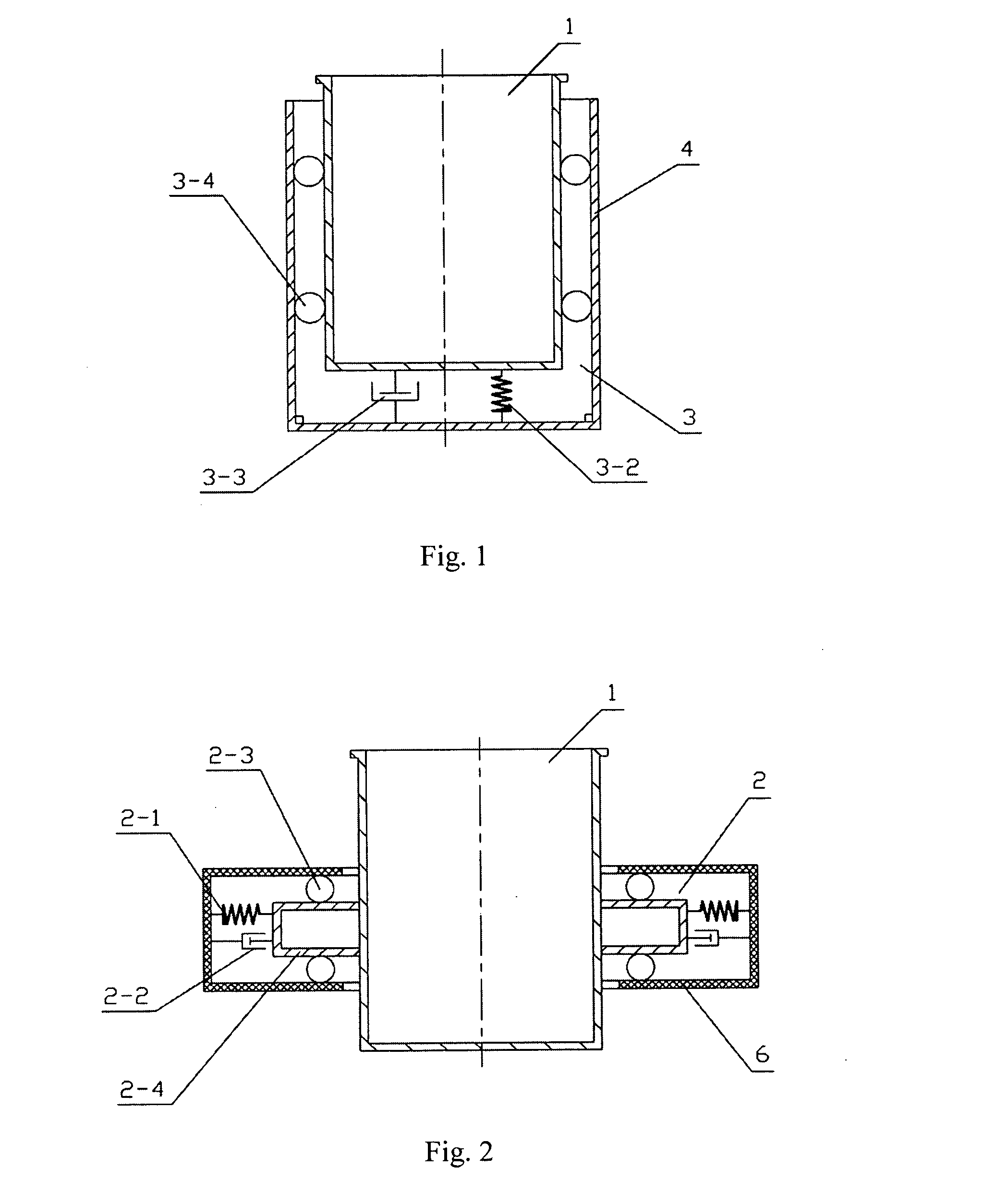
[0037]One embodiment of the invention shown as FIG. 1 includes a spacecraft-link portion 1, a longitudinal vibration attenuation / isolation portion 3, and a LV-link portion 4. The longitudinal vibration attenuation / isolation portion 3 is composed of the longitudinal sliding constraint structure 3-1, the longitudinal elastic element 3-2, the longitudinal damping element 3-3, and the longitudinal bilateral sliding constraint surface 3-4. The bottom of the spacecraft-link portion 1 is connected to the LV-link portion 4 by groups of longitudinal elastic elements 3-2 and the longitudinal damping elements 3-3 in parallel. The exterior surface of the spacecraft-link portion 1 is connected to the interior surface of the LV-link portion 4 by the longitudinal bilateral sliding constraint surface 3-4.

[0038]The spacecraft-link portion 1 and the LV-link portion 4 construct a longitudinal sliding pair which only allows the spacecraft-link portion 1 to translate along the longitudinal direction rel...

example 2

[0039]One embodiment of the invention shown as FIG. 2 includes a spacecraft-link portion 1, a lateral vibration attenuation / isolation portion 2, and a LV-link portion II 6. The lateral vibration attenuation / isolation portion 2 is composed of the lateral elastic element 2-1, the lateral damping element 2-2, the lateral bilateral sliding constraint surface 2-3 and the lateral sliding structure 2-4. The exterior surface of the spacecraft-link portion 1 and the interior of the lateral sliding structure 2-4 are fixed together. The exterior surface of the lateral sliding structure 2-4 is connected to the interior surface of the LV-link portion II 6 by groups of lateral elastic elements 2-1 and lateral damping elements 2-2 in parallel. The lateral sliding structure 2-4 is connected the LV-link portion II 6 by the lateral bilateral sliding constraint surface 2-3.

[0040]The LV-link portion II 6 and the lateral sliding structure 2-4, which is fixed on the spacecraft-link portion 1, construct a...

example 3

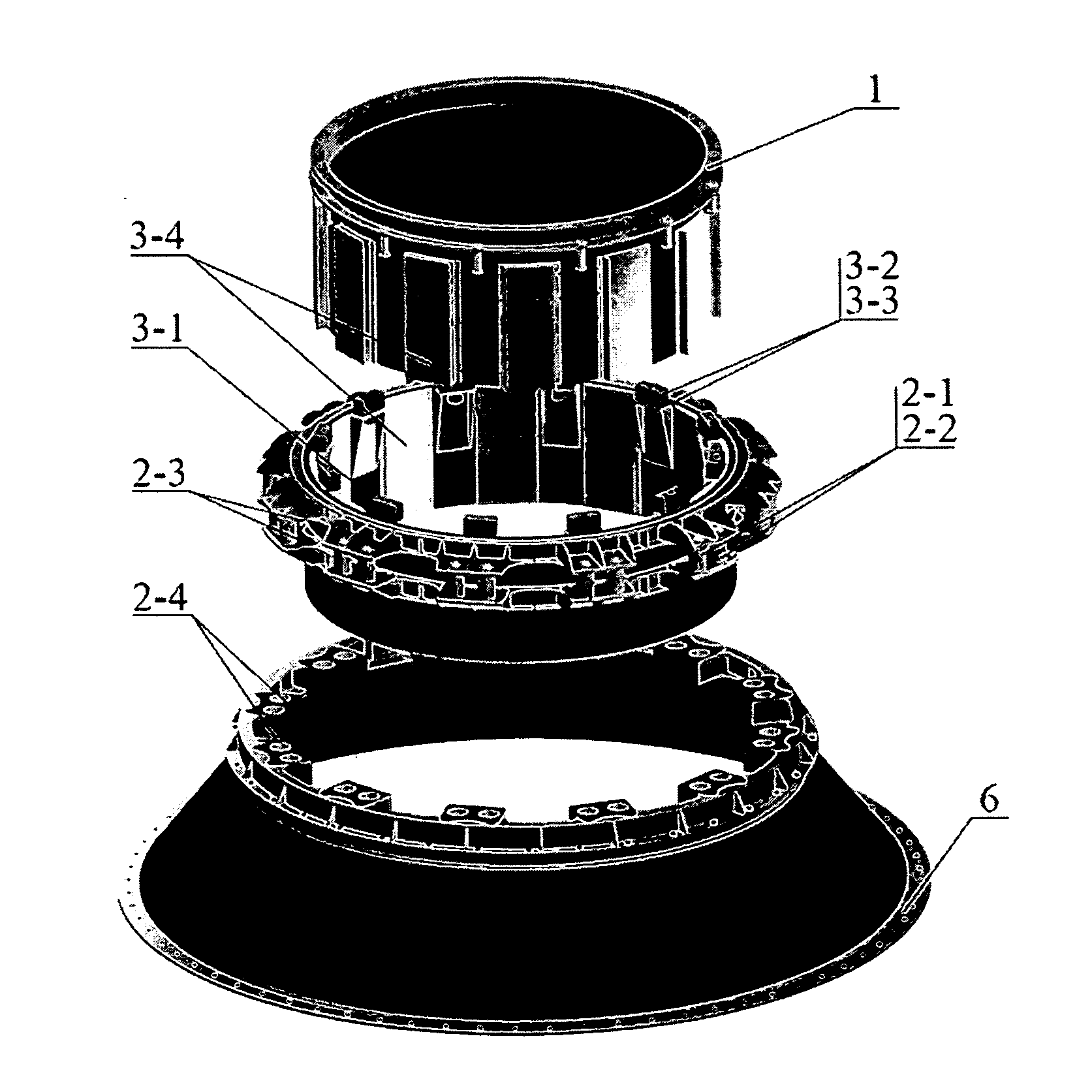
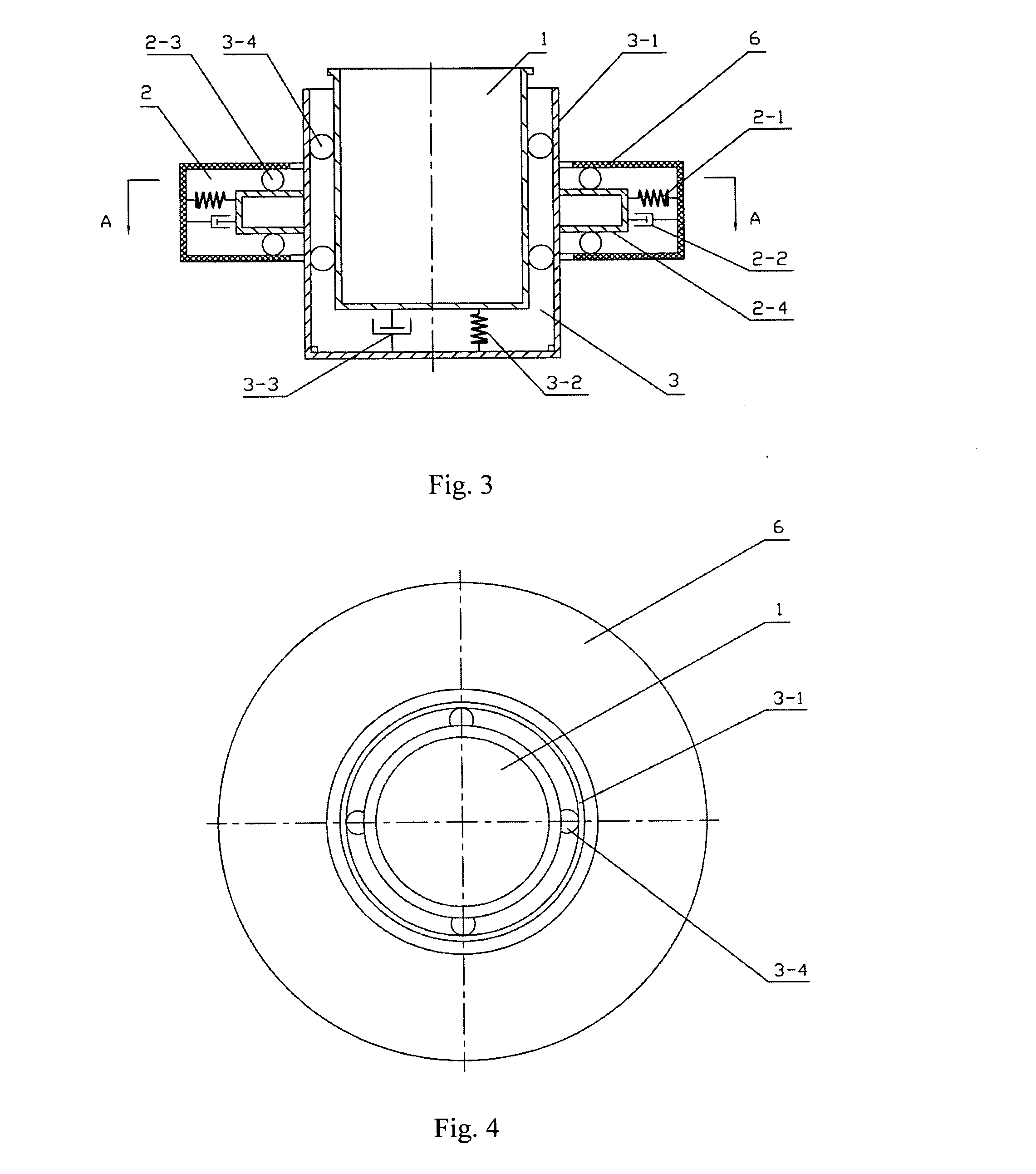
[0041]One embodiment of the invention shown as FIGS. 3-5 includes a spacecraft-link portion 1, a lateral vibration attenuation / isolation portion 2, a longitudinal vibration attenuation / isolation portion 3, and a LV-link portion 6. One engineering realization of this embodiment is shown as FIGS. 9-10, which depict the vibration damping elements in more detail. The lateral vibration attenuation / isolation portion 2 is composed of the lateral elastic element 2-1, the lateral damping element 2-2, the lateral bilateral sliding constraint surface 2-3 and the lateral sliding structure 2-4. The longitudinal vibration attenuation / isolation portion 3 is composed of the longitudinal sliding constraint structure 3-1, the longitudinal elastic element 3-2, the longitudinal damping element 3-3, and the longitudinal bilateral sliding constraint surface 3-4. The bottom of the spacecraft-link portion 1 is connected to the longitudinal sliding constraint structure 3-1 by groups of the longitudinal elas...


PUM


Abstract

The present invention relates to a vibration attenuation / isolation device. An implementation of the invention provides an improved whole-spacecraft vibration attenuation / isolation by separating the vibration load on the spacecraft that arise from the launch vehicle and fairing into longitudinal and lateral components, and effectively attenuates and / or isolates those components. The invention also provides a general method for reducing vibrations in an assembly by using a vibration control device that separates the vibrational forces into perpendicular components that can be separately damped or attenuated.

Description

RELATED APPLICATION[0001]This application is related to Chinese national patent application No. 200610010442.X, filed Aug. 25, 2006, entitled “UNCOUPLED WHOLE-SPACECRAFT VIBRATION ATTENUATION / ISOLATION DEVICE.” The disclosure of the above Chinese national patent application is incorporated by reference in its entirety.Technical Field[0002]This invention relates to a vibration attenuation / isolation device and method that reduces vibrations transmitted between two structures joined into one assembly. The device provides two perpendicular sliding surfaces that separate vibrational forces into perpendicular components, then separately damps or attenuates each of these components. Therefore, it is given the name of Uncoupled Vibration Attenuation / Isolation Devices. One implementation of the invention is a whole-spacecraft vibration attenuation / isolation device and method with improved effectiveness over those known in the art: the invention uses an uncoupler device to separate or uncoupl...

Claims


Application Information

Patent Timeline
Patent Type & Authority Applications(United States)
IPC IPC(8): B64G1/52F16F7/10
CPCF16F15/022B64G1/641
Inventor ZHENG, GANGTIELIU, LIKUNLIANG, LUHE, LING
Owner ZHENG GANGTIE
Why Eureka
Try Eureka