

Removal tool for a filter insert of a liquid filter
A technology for fluid filters and removal tools, applied in the direction of membrane filters, fixed filter elements, filter separation, etc.
- Summary
- Abstract
- Description
- Claims
- Application Information
AI Technical Summary
Problems solved by technology
Method used
Image

Examples
Embodiment Construction
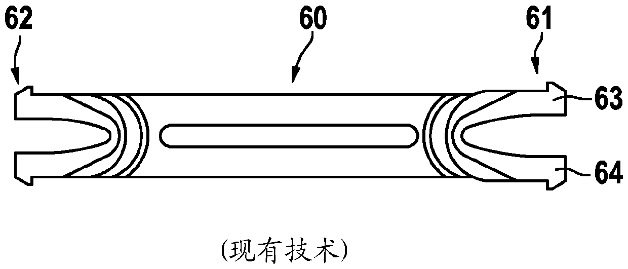
[0055] Figure 1a A prior art removal tool 60 is shown. The removal tool 60 is designed in one piece in the form of an ice cream stick or spatula. In other words, the removal tool has a flat, elongated extension. At the front, distal end 61 , the removal tool 60 has a first hook 63 and a second hook 64 , which are designed in the form of two fork tines. A similar structure also exists at the distal second end 62 of the removal tool 60 . The removal tool 60 has a recess in its central section between the first end 61 and the second end 62 so that it is as flexible as possible and bendable.
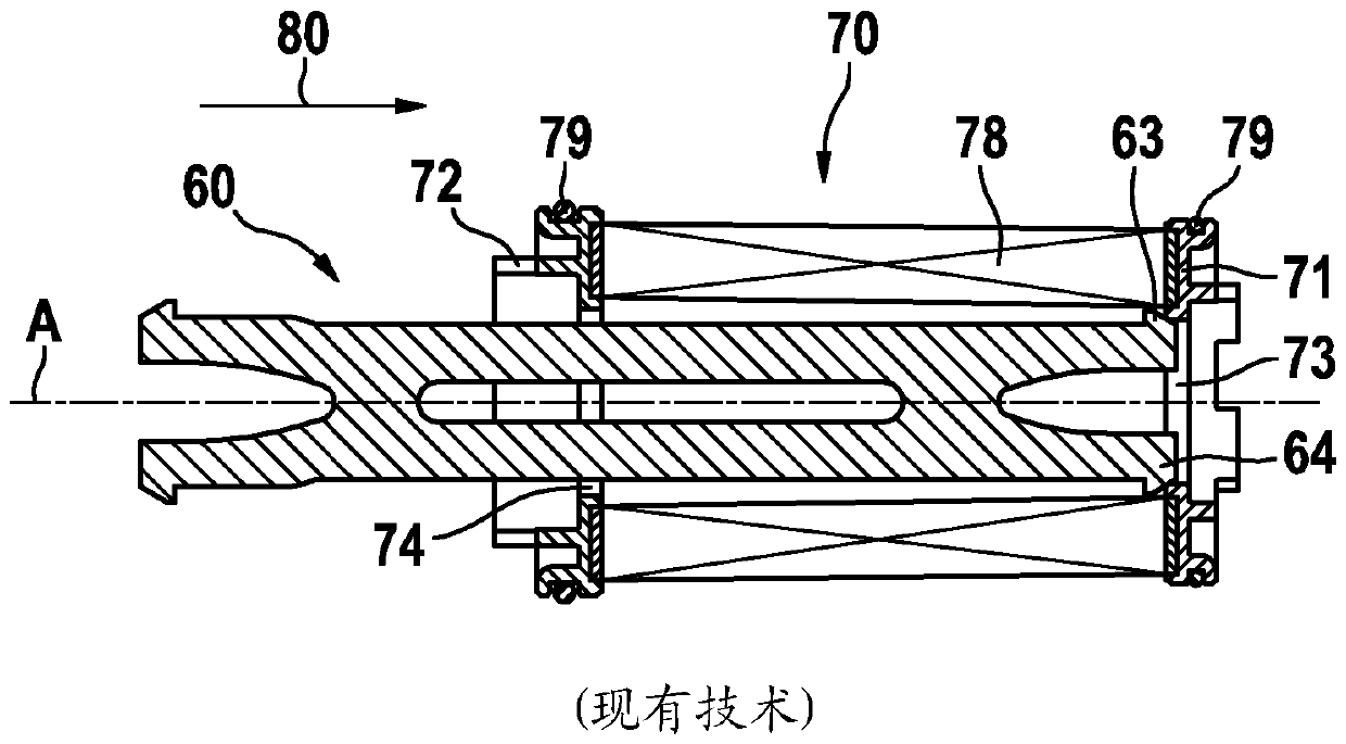
[0056] Figure 1bThe prior art removal tool 60 is shown during insertion into the filter insert 70 along the insertion direction 80 . The filter insert 70 has a hollow cylindrical configuration and extends along the longitudinal axis A. As shown in FIG. The filter insert 70 comprises a first end cap 71 with a first opening 73 and a second end cap 72 with a second opening 74 . The fil...
PUM
 Abstract
Description
Claims
Application Information