Digital camera

Inactive Publication Date: 2008-02-28
PENTAX RICOH IMAGING CO LTD
View PDF9 Cites 12 Cited by
  • Summary
  • Abstract
  • Description
  • Claims
  • Application Information

AI Technical Summary

Benefits of technology

[0006]An object of the present invention is to provide a digital camera, an apparatus / method for sampling image data when compressing image data, or a computer-readable medium that is capable of effectively recording image data without decreasing image resolution.

Problems solved by technology

However, this compression process is not preferable to a digital camera.

Method used


Image

  • Digital camera
  • Digital camera
  • Digital camera

Examples


first embodiment

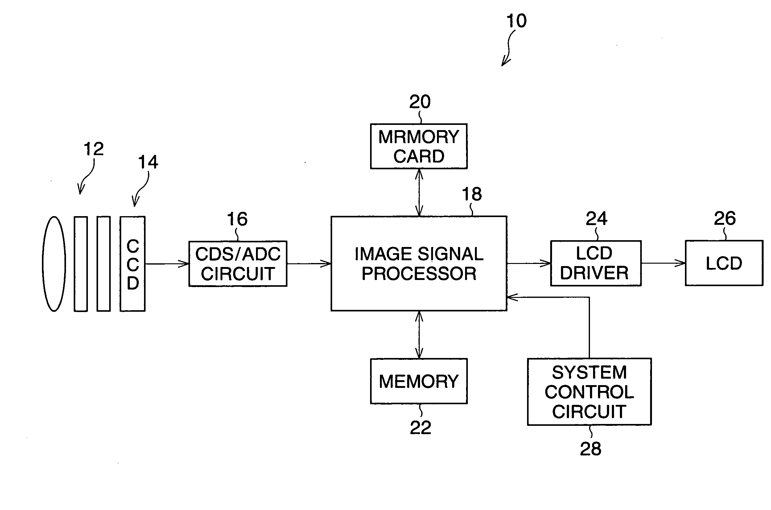
[0019]FIG. 1 is a block diagram of a digital camera according to the

[0020]The digital camera 10 is turned on by depressing a power button (not shown) so that the camera 10 can carry out a photographing process. A system control circuit 28, including a CPU, ROM, and RAM, controls the action of the camera 10, and detects when a release button (not shown) is in a half-depressed or fully depressed position. In the ROM, a program for controlling the action of the camera 10 is stored.

[0021]When a normal photographing mode is selected, a signal process for displaying a moving-image on a LCD monitor 26 is performed. An object image is formed on the light-receiving surface of a CCD 14 by light passing through a photographing optical system 12, so that analog image-pixel signals corresponding to the object image are generated in the CCD 14. The generated image-pixel signals are successively read from the CCD 14 at constant intervals (for example, 1 / 60 seconds interval), and fed to an image si...

second embodiment

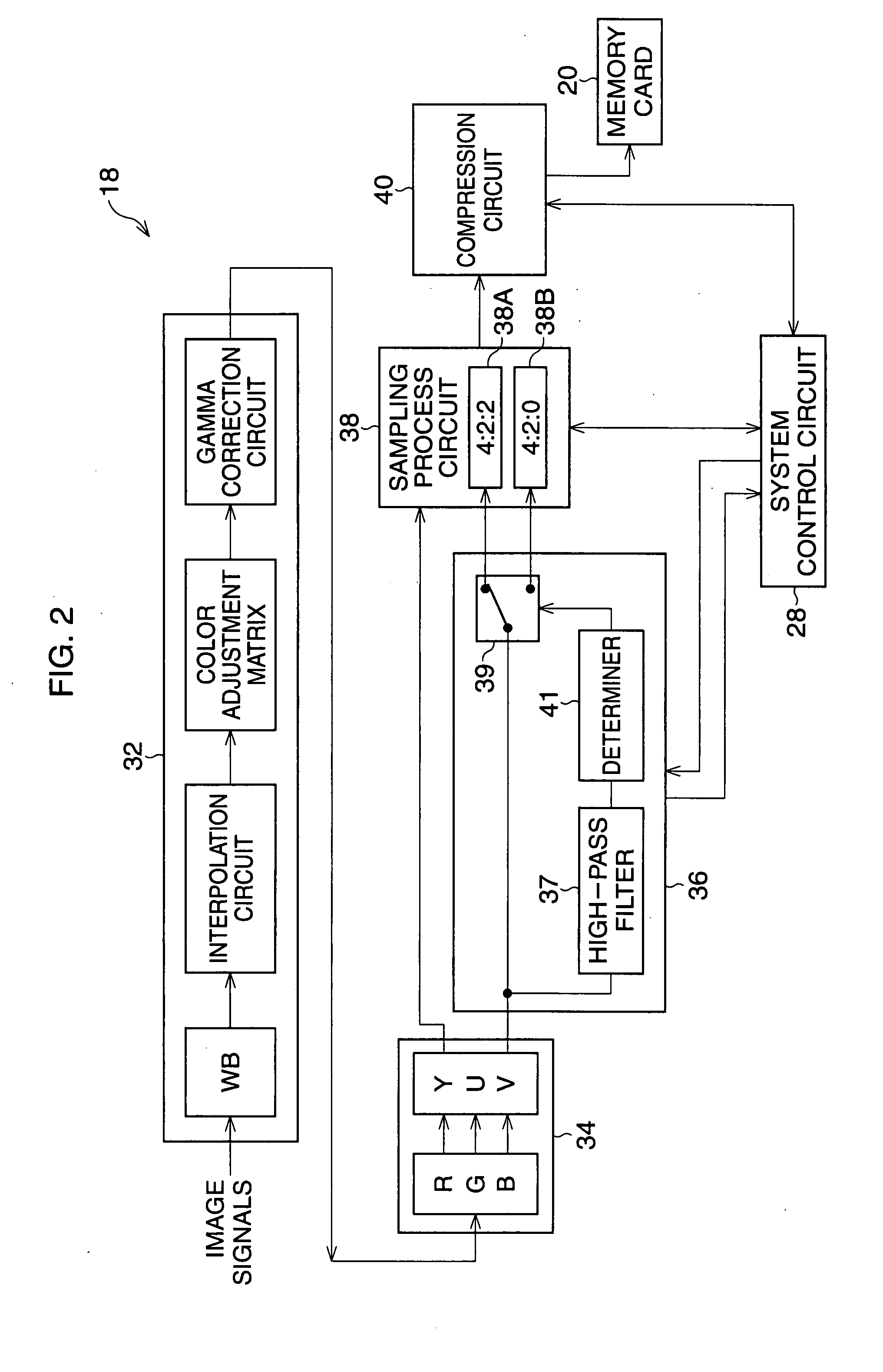
[0038]FIG. 4 is a block diagram of a digital camera according to the A compression circuit 40′ has a DCT processor 42′ and a Huffman processor 44′. A program for setting a ratio of sampling frequencies is stored in a ROM of the system control circuit 28.

[0039]Luminance and color difference signals Y, U, and V, which are output from the color matrix circuit 34, are input to the DCT processor 42 where the luminance and color difference signals Y, U, and V are subjected to the DCT process. Consequently, DCT-processed image data is generated. In the DCT-processed image data, high-frequency components and low-frequency components are separated.

[0040]Based upon the DCT-processed image data, the system control circuit 28 determines whether the sum of absolute values of the high-frequency components exceeds a given value. Then, the system control circuit 28 controls a switch 39′ such that the color difference signals U and V, which is output from the color matrix 34, are fed to the first s...


PUM


Abstract

A digital camera has a signal processor, a high-frequency detector, a sampling processor, and a compression processor. The signal processor generates luminance and color difference data on the basis of image-pixel signals read from an image sensor. The high-frequency detector detects high-frequency components in the color difference data. The sampling processor carries out a sampling process to the luminance and color difference data in accordance with a given ratio of sampling frequencies. Then, the compression processor compresses the sampled luminance and color difference data. When there is a relatively low number of high-frequency components in the color difference data, the sampling processor samples the color difference data with a low sampling frequency.

Description

BACKGROUND OF THE INVENTION[0001]1. Field of the Invention[0002]The present invention relates to a digital camera, electronic equipment with a photographing function, such as a cellular phone, and so on. In particular, it relates to a recording process of image data.[0003]2. Description of the Related Art[0004]In a digital camera, image data is generally subjected to a compression process in accordance with the JPEG. Concretely, luminance data and color difference data are subjected to a sampling process, and a DCT (Discrete Cosine Transform) process and a Huffman coding process are carried out on the sampled luminance and color difference data. Consequently, compressed image data is generated. The ratio of sampling frequencies associated with the luminance and color difference data is predetermined.[0005]In a printer system, to raise the compression factor, a sampling frequency of a low-resolution image is set to a high frequency, whereas a sampling frequency of high-resolution ima...

Claims


Application Information

Patent Timeline
IPC IPC(8): H04N9/73
CPCH04N5/232H04N5/23232H04N9/804H04N5/84H04N9/045H04N5/772H04N23/951H04N23/80
Inventor YAMAMOTO, YASUHIRO
Owner PENTAX RICOH IMAGING CO LTD
Why Eureka
Try Eureka