
Rotary pump having a valve rotor and one or more vane rotors and methods for pumping fluids

Inactive Publication Date: 2008-02-28
JACOBSEN SAM J
View PDF42 Cites 9 Cited by
  • Summary
  • Abstract
  • Description
  • Claims
  • Application Information

AI Technical Summary

Benefits of technology

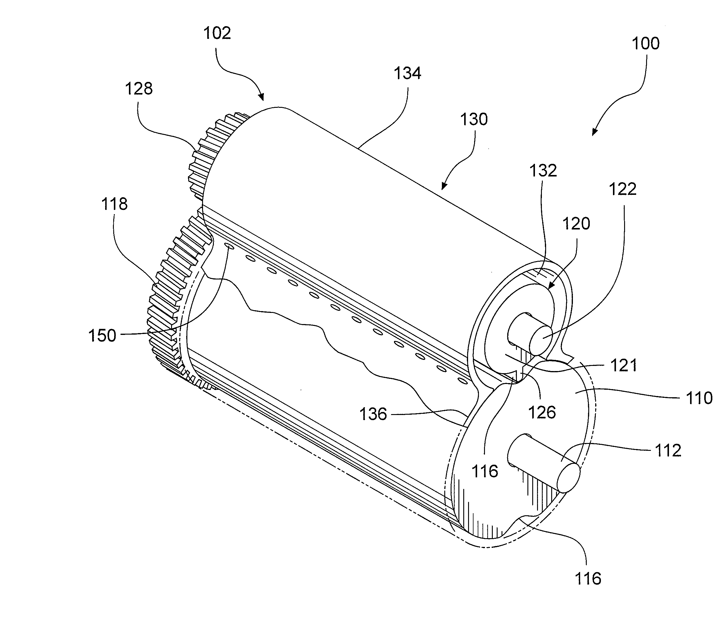
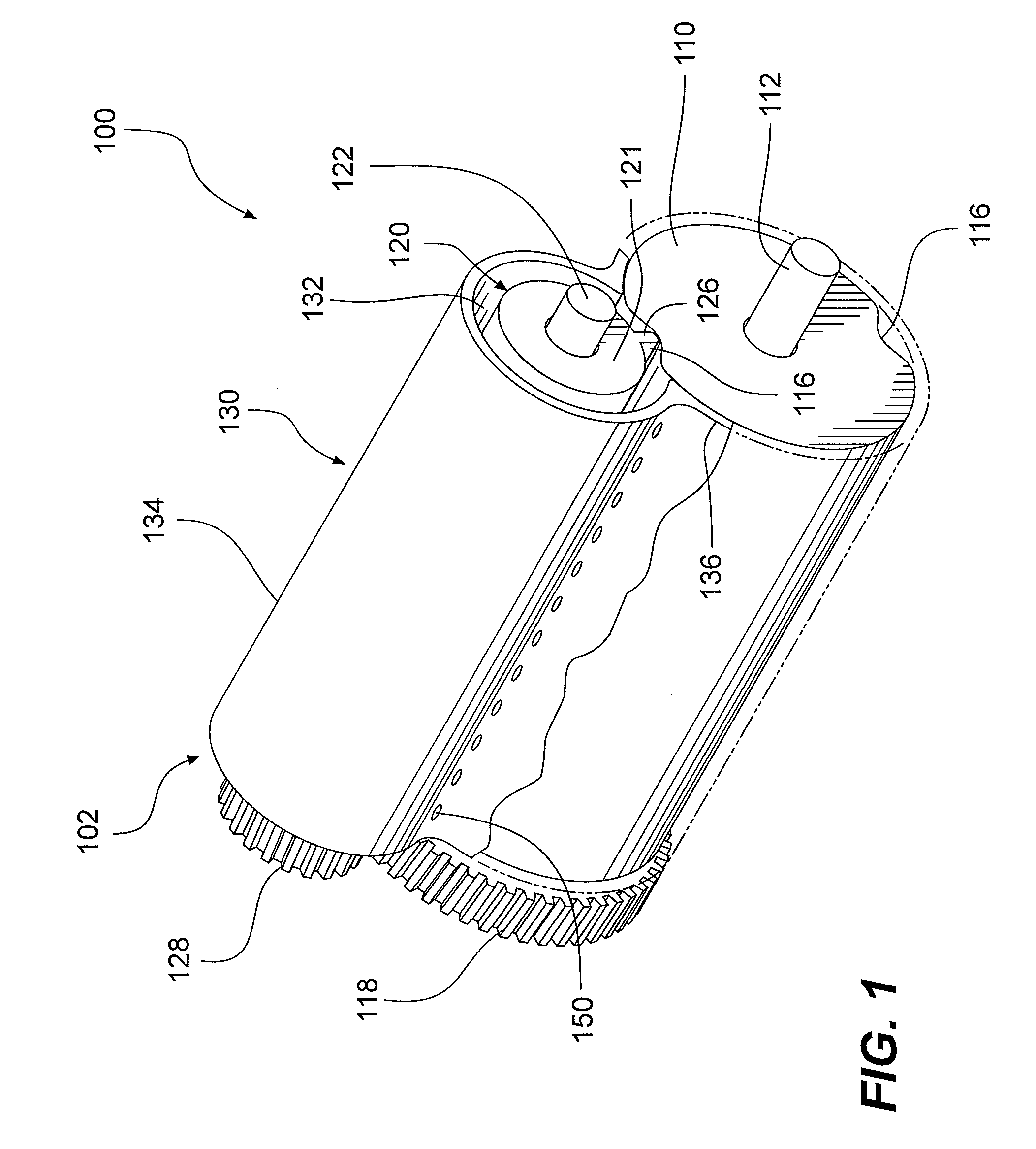
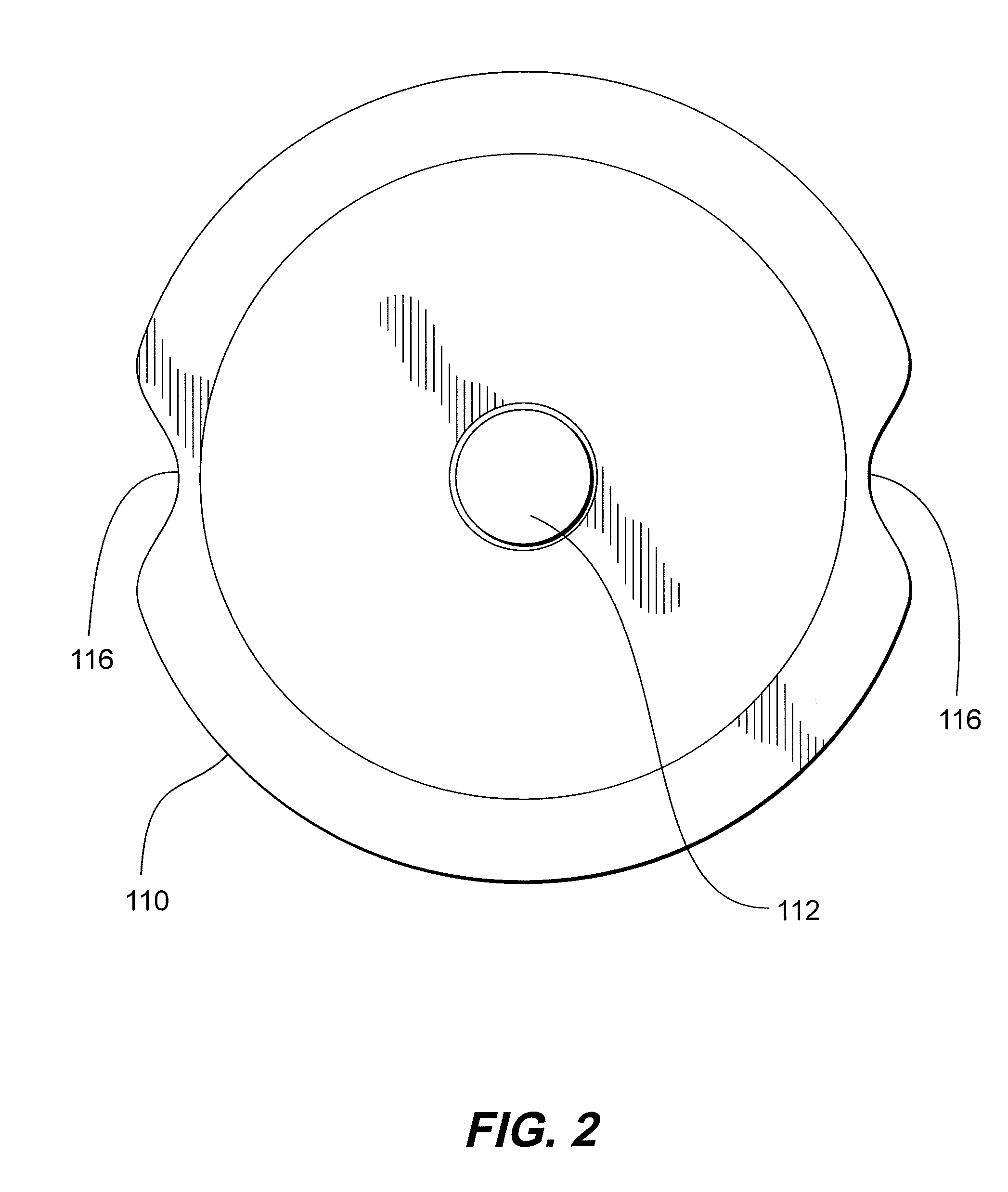
[0035]In various exemplary embodiments, as the vane rotor rotates within the rotor housing portion of the housing, each vane in turn makes an effective seal with the inner surface of the rotor housing portion of the housing. In various exemplary embodiments, at the same time, the vane rotor and the valve rotor also make an effective seal at the point where their respective surfaces interact or closely approach each other. At specific portions of the rotational positions of the vane rotors, each vane is downstream from the one or more discharge openings and upstream of the one or more inlet openings, s

Problems solved by technology

The rotary speed of this type of pump is limited, due to the time required to fill the areas between the teeth with the fluid flowing through the inlet.
This type of pump has a high volumetric efficiency but its speed and displacement are limited due to valve area availability, and it is speed limited due to mechanical limits when converting rotary motion to reciprocating motion.

Method used


Image

  • Rotary pump having a valve rotor and one or more vane rotors and methods for pumping fluids
  • Rotary pump having a valve rotor and one or more vane rotors and methods for pumping fluids
  • Rotary pump having a valve rotor and one or more vane rotors and methods for pumping fluids

Examples


Embodiment Construction

[0014]This invention provides rotary pumps and methods for pumping fluids comprising one or more vane rotors that each have one or more vanes that divide a pump space into an inlet space and a discharge space.

[0015]This invention separately provides rotary pumps and methods for pumping fluids comprising one or more vane rotors that each have one or more vanes that divide a pump space into an inlet space, a displacement space, and a discharge space.

[0016]This invention separately provides rotary pumps and methods for pumping fluids comprising at least one vane rotor that each has a substantially large displacement volume.

[0017]This invention separately provides rotary pumps and methods for pumping fluids comprising one or more vane rotors that each have a vane that interacts with or engages at least one slot formed in a valve rotor as the valve rotor and the one or more vane rotors rotate relative to each other.

[0018]This invention separately provides rotary pumps and methods for pum...


PUM


Abstract

A rotary pump includes a valve rotor and one or more vane rotors positioned around it. Each vane rotor has a vane that engages a slot in the valve rotor as the vane rotor rotates. A housing around the valve rotor and the vane rotor(s) defines a generally constant-radius pump space around each vane rotor and includes inlet and discharge openings associated with each vane rotor. As each vane rotor rotates within the housing, its vane sealingly interacts with the housing, while that vane rotor sealingly interacts with the valve rotor. The vane interacts with the channel, allowing the vane to move past the valve rotor. As the vane rotor rotates, the vane enters the pump space to divide the pump space into at least inlet and discharge portions, while fluid within the discharge portion is discharged or compressed and additional fluid is drawn into the inlet portion.

Description

BACKGROUND OF THE INVENTION[0001]1. Field of the Invention[0002]This invention is directed to rotary pumps having a valve rotor, one or more vane rotors and methods for pumping fluids using rotary pumps having a valve rotor and one or more vane rotors.[0003]2. Related Art[0004]Rotary external or internal tooth, vane and piston pumps are commonly used to compress gases and / or to pump fluids in fluid systems. These types of pumps typically comprise an inlet opening, one or more rotating members and an outlet or discharge opening. The internal and external tooth gear pumps fill the void between teeth with fluid and / or gas at the inlet and, by rotating the teeth, deliver the fluid and / or gas to a transport or displacement area that is provided between the inlet and the discharge. Rotating the teeth further delivers the fluid and / or gas to a discharge area. The gear teeth then mesh together to seal the discharge area from the inlet. This type of pump has a low displacement for the overal...

Claims


Application Information

Patent Timeline
IPC IPC(8): F01C1/08
CPCF01C1/20
Inventor JACOBSEN, SAM J.HUBER, MELVIN F.MELTER, CRAIG H.
Owner JACOBSEN SAM J
Learn More