Mechanical breather valve of vault oil tank

A vault oil tank and breathing valve technology, which is applied in the field of oil tank valves, can solve problems such as small sealing pressure, large sealing pressure, and oil loss, and achieve the effect of preventing impurities from entering, preventing open flames from entering, and effective sealing

Inactive Publication Date: 2020-06-09
孙淑芳
View PDF9 Cites 0 Cited by
  • Summary
  • Abstract
  • Description
  • Claims
  • Application Information

AI Technical Summary

Problems solved by technology

[0003] When the oil tank breathes, a large amount of mixed oil and gas will overflow when the valve body is opened, which will cause a large amount of oil and gas to volatilize into the air, resulting in a large amount of oil waste. When encountering an open flame at a long distance, there will also be a safety hazard. At the same time, when the external air enters the inside of the oil pipe through the respiration of the breathing valve, impurities in the air, such as water vapor, dust, etc., will enter the inside of the oil tank, which will cause When the oil in the oil tank is polluted and the quality becomes low, although some mechanical breathing valves can block the volatilization of oil and gas, a large amount of volatilized oil and gas cannot be collected and cannot be recycled
[0004] The currently used mechanical breathing valve is sealed with a ring-shaped smooth gasket during use. This sealing method requires a relatively large sealing pressure to perform better sealing. The positive pressure valve plate and the negative pressure valve plate are used for sealing. During the sealing process, the sealing pressure is not large, which makes the sealing effect not good, easily leads to the loss of oil products, and makes the control effect of the breathing valve worse

Method used


Image

  • Mechanical breather valve of vault oil tank
  • Mechanical breather valve of vault oil tank
  • Mechanical breather valve of vault oil tank

Examples


Embodiment Construction

[0019] The following will clearly and completely describe the technical solutions in the embodiments of the present invention with reference to the accompanying drawings in the embodiments of the present invention. Obviously, the described embodiments are only some, not all, embodiments of the present invention. Based on the embodiments of the present invention, all other embodiments obtained by persons of ordinary skill in the art without making creative efforts belong to the protection scope of the present invention.

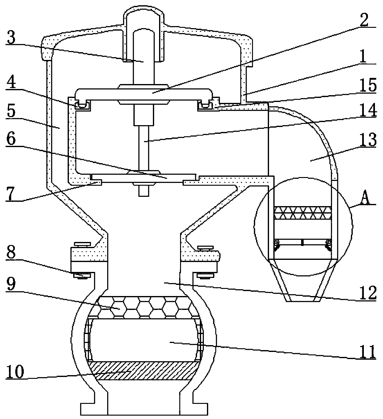
[0020] see Figure 1-3 , a mechanical breather valve for a vaulted oil tank, including a valve body shell 1, a negative pressure valve seat 15 is installed on the front of the inner cavity of the valve body shell 1, and the inner cavity of the valve body shell 1 is located above the negative pressure valve seat 15. Connected with a negative pressure valve plate 2, the top of the negative pressure valve plate 2 is fixedly connected with a first movable clamping...


PUM


Abstract

The invention relates to the technical field of valves of oil tanks, and discloses a mechanical breather valve of a vault oil tank. The mechanical breather valve comprises a valve body casing; a negative-pressure valve seat is mounted on the front side of an inner cavity of the valve body casing; a negative-pressure valve plate is movably clamped in the inner cavity of the valve body casing and located above the negative-pressure valve seat; a first moving clamping column is fixedly connected at the top of the negative-pressure valve plate; and a positive-pressure valve seat is mounted on thefront side of the inner cavity of the valve body casing and located below the negative-pressure valve seat. According to the mechanical breather valve of the vault oil tank, an oil tank communicatingseat as well as an upper cylindrical film, a lower cylindrical film and an oil storage cavity mounted in the oil tank communicating seat is arranged at the bottom of the valve body casing, so that oilvapor at the oil tank cannot pass through the upper cylindrical film, and then the oil vapor cannot be volatilized; meanwhile, the outside air can enter the oil tank, then the oil tank can have the respiratory action, the oil vapor and the air can pass through the lower cylindrical film, and then the oil vapor is liquefied and stored in the oil storage cavity.

Description

technical field [0001] The invention relates to the technical field of oil tank valves, in particular to a mechanical breather valve for vaulted oil tanks. Background technique [0002] The mechanical breathing valve is an important accessory to protect the safety of the oil tank. It is installed on the top plate of the oil tank. Its function is to keep the airtightness of the oil tank under normal circumstances and reduce the evaporation loss of oil products to a certain extent. , it can automatically ventilate and adjust to balance the internal and external pressure of the oil tank, which plays a safe role in the oil tank. [0003] When the oil tank breathes, a large amount of mixed oil and gas will overflow when the valve body is opened, which will cause a large amount of oil and gas to volatilize into the air, resulting in a large amount of oil waste. When encountering an open flame at a long distance, there will also be a safety hazard. At the same time, when the exter...

Claims


Application Information

Patent Timeline
IPC IPC(8): B65D90/32
CPCB65D90/32
Inventor 不公告发明人
Owner 孙淑芳
Why Eureka
Try Eureka