Slot-in disk drive device

Inactive Publication Date: 2008-02-28
QUANTA STORAGE INC
View PDF5 Cites 6 Cited by
  • Summary
  • Abstract
  • Description
  • Claims
  • Application Information

AI Technical Summary

Benefits of technology

[0008]The invention is directed to a disk drive device having a receiving bar that can be fixed at positions stepwise so that different sizes of di

Problems solved by technology

However, discs of different sizes cannot be embedded with a spindle motor for rotating the disc correctly until the disc reach a playing position in the disk drive device without error, or otherwise the optical disc is jammed in the disk drive device.
Thus, the device tends to have an error, or even the disc and the disk drive device tend to be damaged.
However, the guiding rod and the bar-linkage mechanism have to successively guide the disc to be aligned with the spindle motor, and the loading/ejecting mechanism is too complicated.

Method used


Image

  • Slot-in disk drive device
  • Slot-in disk drive device
  • Slot-in disk drive device

Examples


Example

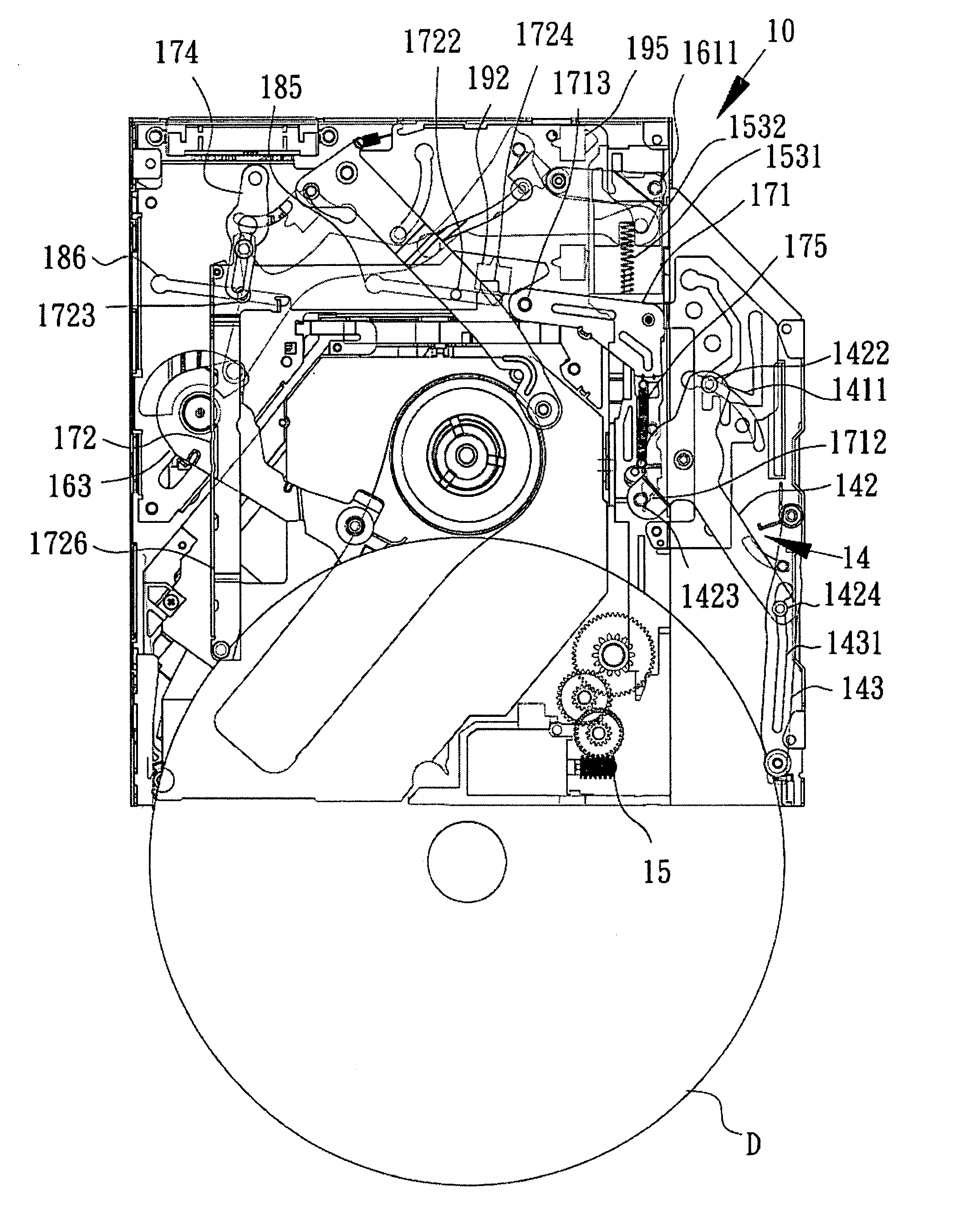
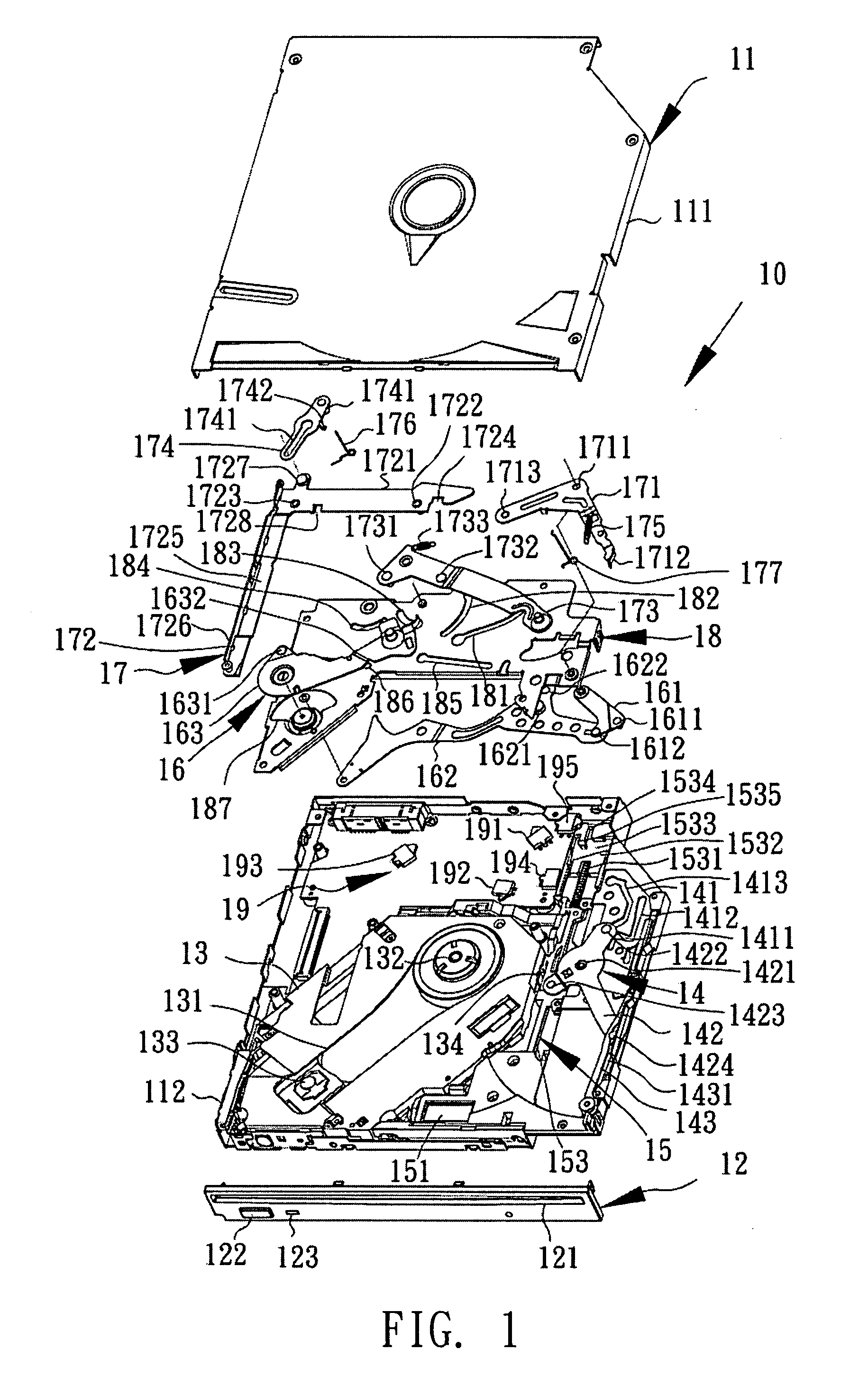
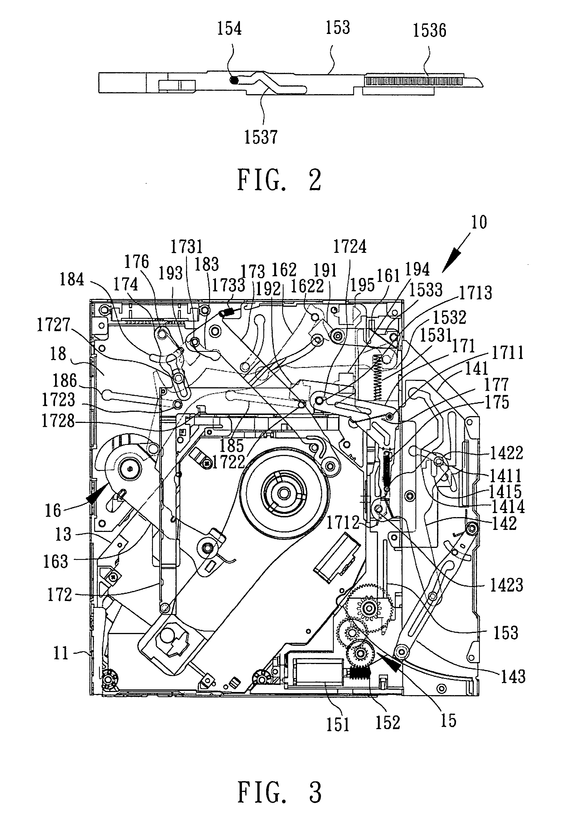
[0025]FIG. 1 is an exploded view showing components of a slot-in disk drive device according to the invention. Referring to FIG. 1, a slot-in disk drive device 10 of the invention includes a casing 11, a panel 12, a traverse 13, a loading unit 14, a drive unit 15, an ejecting unit 16, a receiving unit 17, a substrate 18 and a sensing unit 19. The ejecting unit 16 and the receiving unit 17 actuate the sensing unit 19 to sense a disc D (see FIG. 4) inserted into the disk drive device 10, and enable the drive unit 15 to move the loading unit 14 to push the disc D into the disk drive device 10, and further move the receiving unit 17 to guide the disc D to a predetermined position. Then, the traverse 13 rises to embed with the disc, rotates the disc D and then plays the disc or ejects the disc.

[0026]The casing 11 is composed of an upper case 111 and a lower case 112, which cover a hollow space for accommodating a disc drive mechanism for driving the disc D into and out of the casing 11. ...


PUM


Abstract

A slot-in disk drive device has a drive unit for providing power to move a slider and thus a sliding plate attached to the slider. Guiding slots on the sliding plate rotate a transmission bar. A guide pin is disposed on the transmission bar and moves with a loading stick. One end of a receiving bar is formed with a locking slot. A substrate having inclined slots arranged in parallel and used for guiding the receiving bar. A locking member mounted on the disk drive device has a stopper edge located on moving path of projecting guide pin of the transmission bar and a locking pin. One end of a pulling spring is fixed to the locking member so that the locking pin locks with the locking slot. One end of a restoring bar is mounted on the substrate, and a restoring torsion spring supports and restores the receiving bar.

Description

[0001]This application claims the benefit of Taiwan application Serial No. 95131268, filed Aug. 24, 2006, the subject matter of which is incorporated herein by reference.BACKGROUND OF THE INVENTION[0002]1. Field of the Invention[0003]The invention relates in general to a slot-in optical drive, and more particularly to an apparatus for determining and guiding discs of different sizes to be loaded and ejected in a slot-in disk drive device.[0004]2. Description of the Related Art[0005]Typical disk drive devices may be mainly classified into a tray type disk drive device and a slot-in disk drive device. The tray type disk drive device has a tray for supporting a disc, and the tray is pushed into or slides out of the disk drive device so that the disc reaches a specific position or is ejected. The disc only has to be directly inserted into an inlet of the slot-in disk drive device, and the loading / ejecting mechanism can automatically suck the disc in and guide the disc to the positioning...

Claims


Application Information

Patent Timeline
IPC IPC(8): G11B17/04
CPCG11B17/051
Inventor CHIOU, YAO-JIATSAI, YAO-CHINGKUO, YAO-TINGWU, JEN-CHEN
Owner QUANTA STORAGE INC
Why Eureka
Try Eureka