Multi-rotor unmanned aerial vehicle for fast surveying and surveying method of multi-rotor unmanned aerial vehicle

A multi-rotor UAV, a fast technology, applied in the field of aerial surveying and mapping, can solve the problems of low UAV surveying and mapping accuracy, poor timely measurability, time-consuming and labor-intensive, etc., and achieve the effect of convenient and efficient images, easy to carry, and small size

Inactive Publication Date: 2015-03-04
安徽靓马信息科技股份有限公司
View PDF13 Cites 96 Cited by
  • Summary
  • Abstract
  • Description
  • Claims
  • Application Information

AI Technical Summary

Problems solved by technology

[0008] The purpose of the present invention is to solve the problems of low surveying and mapping accuracy of existing drones, the need to calculate and correct a large amount of data in the later stage, time-consuming and laborious, and poor timely measurability, and provide a fast surveying and mapping multi-rotor drone and its surveying and mapping method; The unmanned aerial vehicle provided by the present invention has a simple structure, and the loaded camera can be adjusted at any time according to the flying attitude of the unmanned aerial vehicle, and the shooting angle perpendicular to the ground surface is always maintained. The surveying and mapping method can quickly obtain the surveying and mapping results without the need for later-stage data calculation and correction, and the surveying and mapping accuracy and efficiency are high; in addition, the entire UAV frame of the present invention adopts a detachable or foldable structure, and is placed in a storage box when it is not in use It is easy to transport and carry, and can be assembled quickly when in use, with strong practicability

Method used


Image

  • Multi-rotor unmanned aerial vehicle for fast surveying and surveying method of multi-rotor unmanned aerial vehicle
  • Multi-rotor unmanned aerial vehicle for fast surveying and surveying method of multi-rotor unmanned aerial vehicle
  • Multi-rotor unmanned aerial vehicle for fast surveying and surveying method of multi-rotor unmanned aerial vehicle

Examples


Embodiment 1

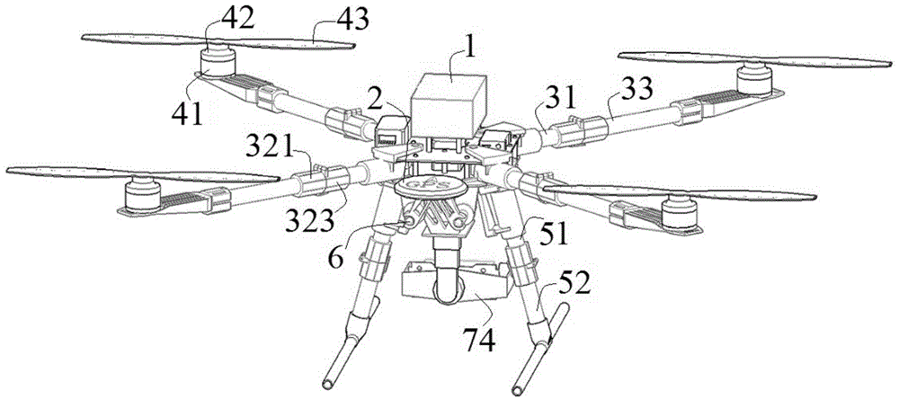
[0048] see figure 1 , a fast surveying and mapping multi-rotor unmanned aerial vehicle of this embodiment includes a frame, a flight lifting mechanism, a cloud platform mechanism and a control mechanism, wherein:

[0049] The frame extends four arms along its body, and the four arms are arranged at equal intervals around the body to ensure the flight stability of the UAV, and a tripod is provided at the bottom of the body. In this embodiment, the machine arm includes a first machine arm 31 and a second machine arm 33, and the root of the first machine arm 31 (that is, a position close to the body) is provided with a folding member, and the first machine arm 31 and the second machine arm 33 pass through The folders are connected. The tripod includes an upper tripod arm 51 and a lower tripod arm 52, the root of the upper tripod arm 51 is provided with a folder, and the upper tripod arm 51 and the lower tripod arm 52 are also connected by a folder. For the specific structure of...


PUM


Abstract

The invention discloses a multi-rotor unmanned aerial vehicle for fast surveying and a surveying method of the multi-rotor unmanned aerial vehicle, and belongs to the technical field of aviation surveying. The multi-rotor unmanned aerial vehicle comprises a rack, flight lifting mechanisms, a cloud deck mechanism and a control mechanism, wherein four plane arms extend out from the rack along a plane body, the lower part of the plane body is provided with foot stools, the plane arms and the foot stools are of foldable structures; and the flight lifting mechanisms are arranged at tail ends of the four plane arms, the cloud deck mechanism is mounted at the bottom of the unmanned aerial vehicle body through a mounting rod; the cloud deck mechanism is provided with a camera and is used for regulating an optical axis of the camera to be always perpendicular to the ground; and the control mechanism is used for controlling the unmanned aerial vehicle to fly to the appointed height and regulating the overturn of the cloud deck mechanism. The surveying method disclosed by the invention can be used for determining the relation between the shooting height and the imaging proportion by analyzing camera lens parameters, and then setting the flight line of the unmanned aerial vehicle. Through the adoption of the unmanned aerial vehicle, the surveying result can be fast obtained, and the surveying precision and efficiency are high.

Description

technical field [0001] The invention relates to the technical field of aerial surveying and mapping, and more specifically, relates to a rapid surveying and mapping multi-rotor unmanned aerial vehicle and a surveying and mapping method thereof. Background technique [0002] With the rapid development of electronic technology, small drones have made significant breakthroughs in remote control, battery life, and flight quality. They have become a new aerial remote sensing method that has emerged in recent years, and are generally considered by the remote sensing community to have good development. prospect. However, the vast majority of UAVs currently in use are not designed for the surveying, mapping and remote sensing industry. Although a simple model airplane also has a flight control system, it can also realize automatic driving and continuous photography in the air. However, during the flight operation, because the UAV is easily affected by the airflow, it will produce i...

Claims


Application Information

Patent Timeline
Patent Type & Authority Applications(China)
IPC IPC(8): B64C27/08B64D47/08
Inventor 杜绍林王燕王楠楠
Owner 安徽靓马信息科技股份有限公司
Why Eureka
Try Eureka