Hand plane with reverse angle frog

a reverse angle, frog technology, applied in the direction of dovetail work, woodworking apparatus, manufacturing tools, etc., can solve the problems of difficult grinding and hone of cutting irons, ergonomics of the user's handgrip on the tote, and the opportunity for vibration and flex of irons

Inactive Publication Date: 2008-03-06
BLUM GARY JOSEPH
View PDF15 Cites 4 Cited by
  • Summary
  • Abstract
  • Description
  • Claims
  • Application Information

AI Technical Summary

Benefits of technology

[0022]The hand plane of the present invention includes a base with a sole and a throat, and opposite front and rear ends. A rear handle is provided on the base adjacent the rear end, and a front knob is provided on the base adjacent the forward end. A reverse angle frog is mounted in the base and extends upwardly and forwardly from the throat. A blade is mounted on the frog for planing wood. The blade may be a cutting blade or a ...

Problems solved by technology

One of the primary problems with the conventional metal plane 10 is the ergonomics of the user's handgrip on the tote 18.
Also, the large, cutting iron is difficult to grind and hone.
Another problem with this type prior art plane is that the pressure from the lever cap 32 or the clamping lever assembly 40 is applied to the cap iron behind the cutting edge of the iron 28.
This creates opportunities for vibration and flex of the iron 28.
Since the wood is subject to warping, the iron may not seat properly.
While the large iron 50...

Method used


Image

  • Hand plane with reverse angle frog
  • Hand plane with reverse angle frog
  • Hand plane with reverse angle frog

Examples


Embodiment Construction

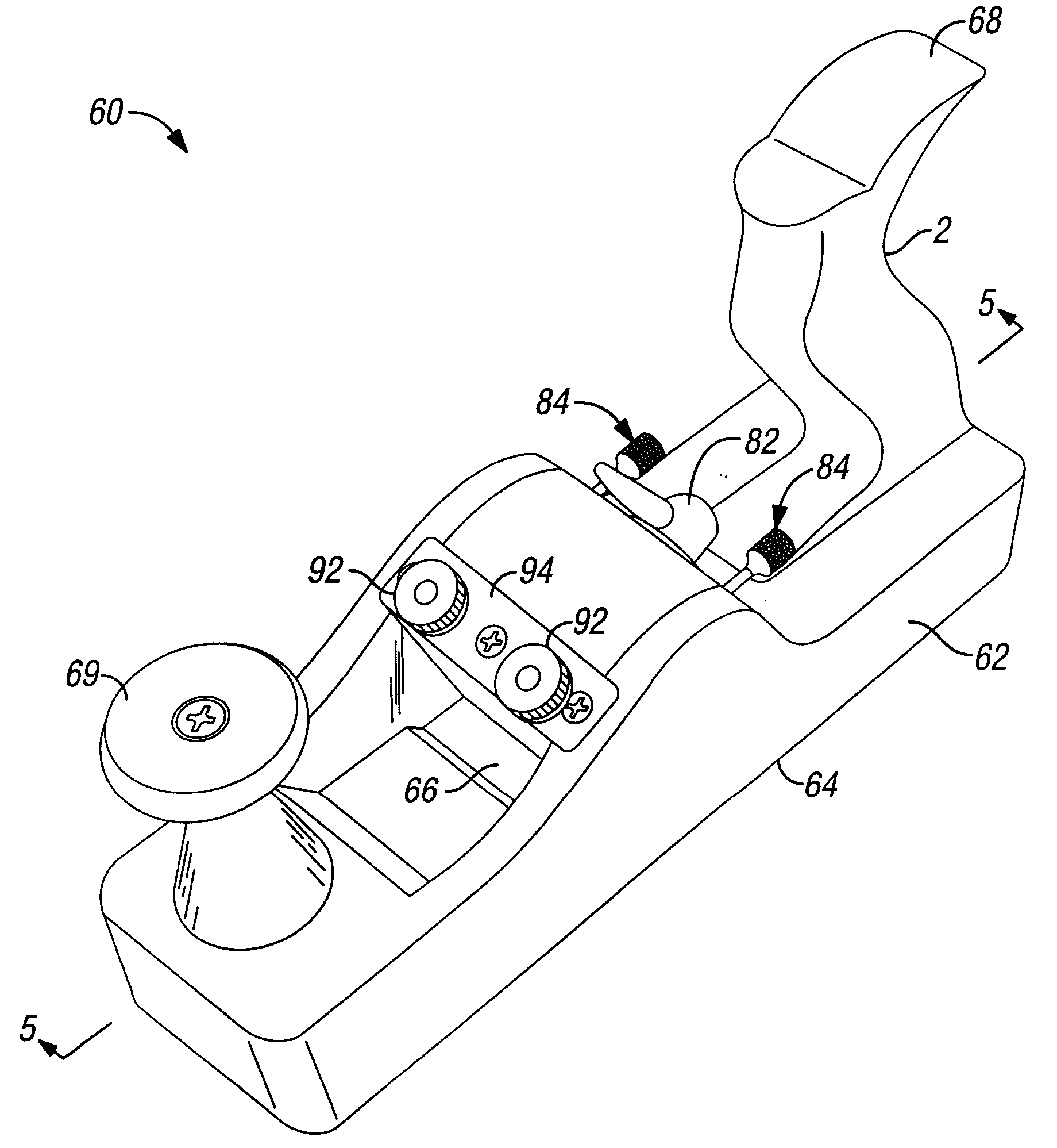
[0035]One embodiment of the improved hand plane of the present invention is shown in FIGS. 3-6. The improved hand plane 60 includes a base 62 with a bottom surface or sole 64 and a throat 66 which extends through the base 62 so as to define a mouth 67 on the sole 64. A rear tote or handle 68 is provided adjacent a rearward end of the plane 60, while a front handle or knob 69 is provided adjacent the front end of the plane 60.

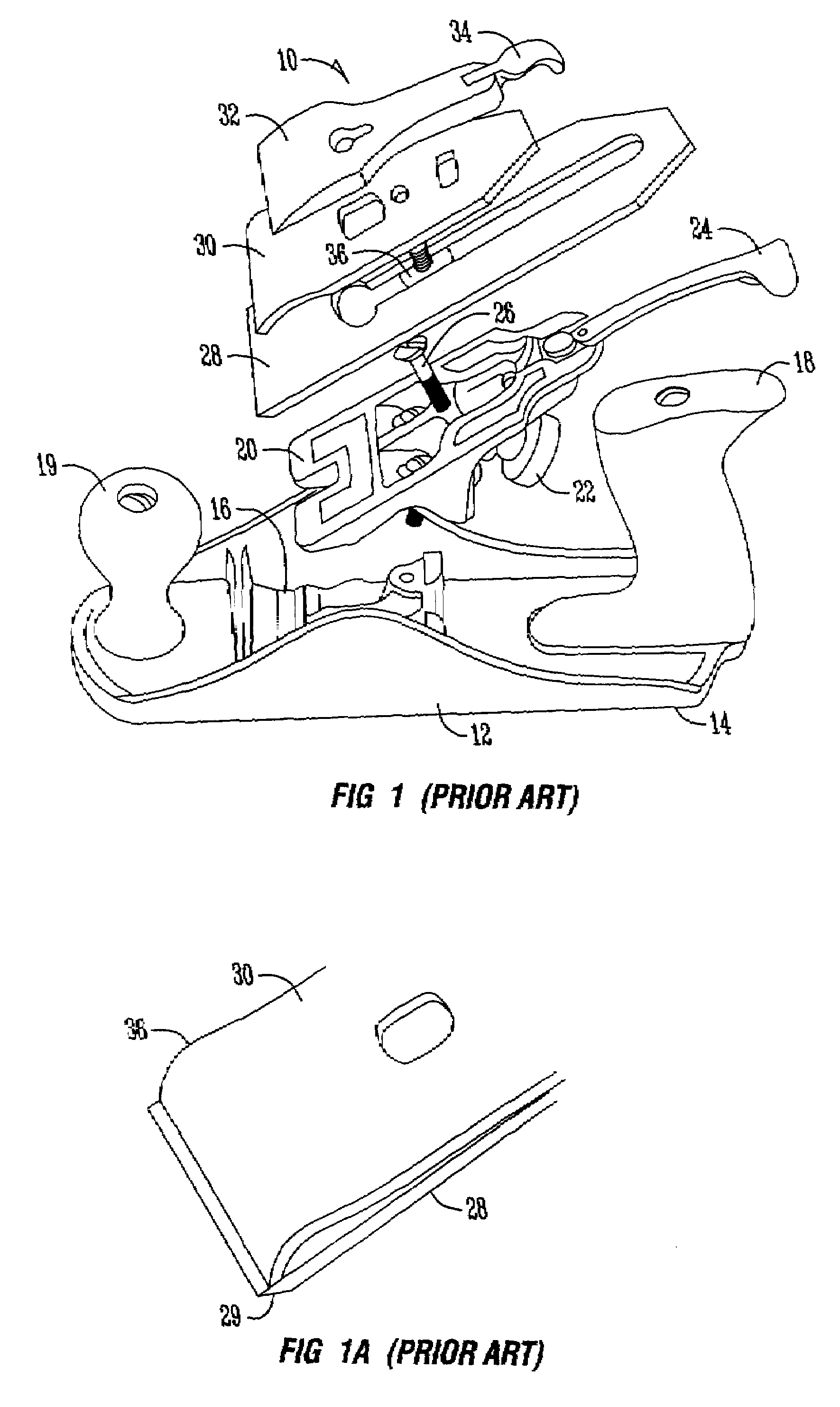
[0036]A frog 70 is mounted in the throat 66 in a reverse angle, as compared to the prior art frog 20 shown in FIG. 1. The frog 70 extends upwardly and forwardly, as best seen in FIG. 5. A cutting blade or iron 72 is mounted on the bottom of the frog 70, and sandwiched between the frog 70 and a backup iron 74. A plurality of screws 76 extend through holes in the backup iron 74 and through slots in the blade 72 for threaded receipt in the bottom of the frog 70. Thus, when it is time t0 sharpen or dispose of the blade 72, the screw 76 need only be loosened slightly...


PUM


Abstract

The improved hand plane of the present invention is used for planing wood, and includes interchangeable frog and blade assemblies. The plane includes a base with a sole and a throat, and a rear handle on the base adjacent the rear end. The frog is mounted in the base and extends upwardly and forwardly from the throat in a reverse angle so as to avoid interference with the handle. A blade is mounted to the frog with attachment screws accessible through the mouth of the throat in the sole of the plane. A pair of screws allows for depth and lateral positioning of the blade.

Description

BACKGROUND OF THE INVENTION[0001]Hand planes have been used for hundreds of years to smooth the surface of wood. A hand plane works when a woodworker pushes or pulls the plane across the surface of the wood which allows the sharp blade or iron to shear off a thin layer of wood, thereby smoothing the wood surface.[0002]FIG. 1 shows an exploded view of a prior art metal hand plane. The hand plane assembly 10 has a base 12, with a bottom surface or sole 14. The base 12 has an opening in the sole 14 which is called the throat 16. Attached to the base 12 is a rear handle or tote 18 and a front knob 19. A device called a frog 20 extends upward from the inside of the base 12. The frog 20 extends rearwardly from the throat 16 towards the tote 18, and holds the cutting blade, which is known as the iron 28. The user can turn the depth adjuster 22 which allows the iron 28 to extend farther through the throat 16. Adjustment of the iron 28 depth allows the iron 28 to engage a deeper or shallower...

Claims


Application Information

Patent Timeline
IPC IPC(8): B27F1/00
CPCB27G17/02
Inventor BLUM, GARY JOSEPH
Owner BLUM GARY JOSEPH
Why Eureka
Try Eureka