
Combined device for analytical measurements

Inactive Publication Date: 2008-03-06
SABLE SYST INT
View PDF6 Cites 15 Cited by
  • Summary
  • Abstract
  • Description
  • Claims
  • Application Information

AI Technical Summary

Benefits of technology

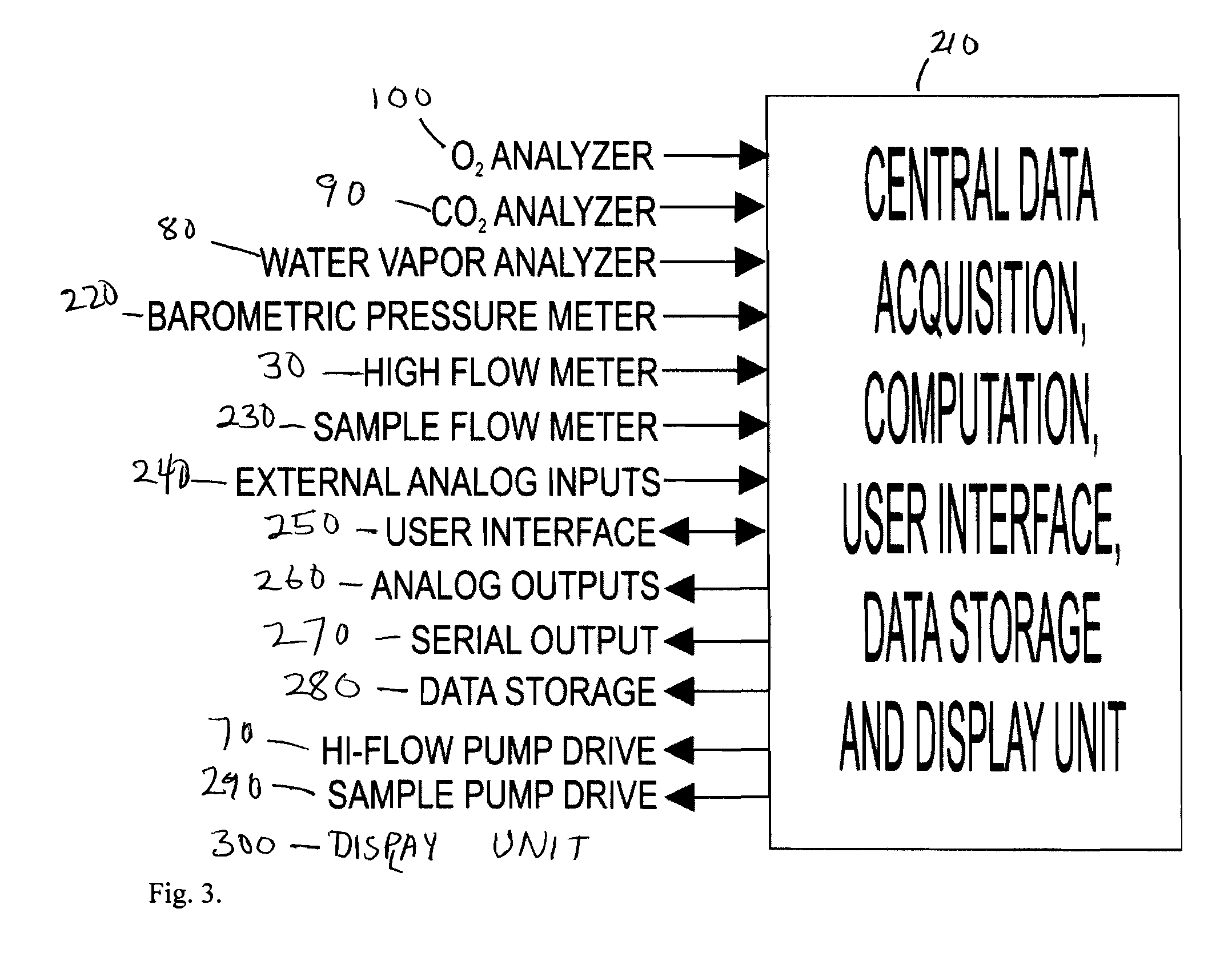
[0007] In another embodiment, the system's oxygen analyzer is a fuel cell, or a zirconia cell. Alternately, the system's oxygen analyzer is based on a measurement principle, such as paramagnetism or optical fluorescence. Additionally, the system can provide calculation of the saturated water vapor pressure obtained at the site of the RH analyzer. As another option, the system can provide conversion of the corrected or uncorrected RH to water vapor activity and then multiply by saturated water vapor pressure to determine the actual water vapor pressure obtained at the RH sensor. As another option, the system can combine the barometric pressure with the water va

Problems solved by technology

Often no final calculations of respiratory data could be performed in the field.
Deploying and powering these multiple devices in the field was a nightmare, often obstructing the intended research or application.
Merely jamming disparate instruments together in a so-called “metabolic cart” was not satisfactory for field, portability and ruggedness.
In addition, such units were generally oriented to clinical use on humans, and their operating assumptions are usually grossly simplistic and inflexible, making them unsuitable for publication-quality research.
Strangely, the need for a research grade; field-oriented, integrated respirometry instrument was not addressed by any firm.
But it still did not solve the problem of multiple instruments: one device for carbon dioxide and oxygen and an additional device for water vapor and other measurements.
In addition, it had a limited flow capacity.

Method used


Image

  • Combined device for analytical measurements
  • Combined device for analytical measurements
  • Combined device for analytical measurements

Examples


Embodiment Construction

[0015] In the following detailed description, references made to the accompanying drawings which form a part hereof and in which is shown by way of illustration specific embodiments in which the invention may be practiced. These embodiments are described in sufficient detail to enable those skilled in the art to practice and, use the invention, and it is to be understood that other embodiments may be utilized in that electrical, logical, and structural changes may be made without departing from the spirit and scope of the present invention. The following description is, therefore, not to be taken in a limiting sense and the scope of the present invention is defined by the appended claims and equivalents thereof.

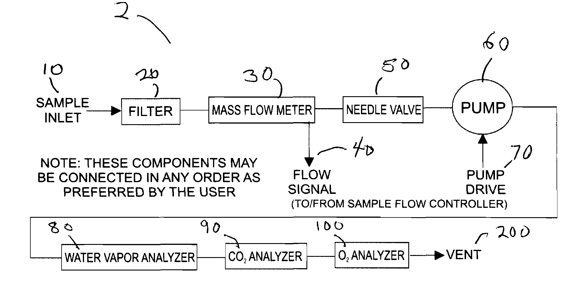
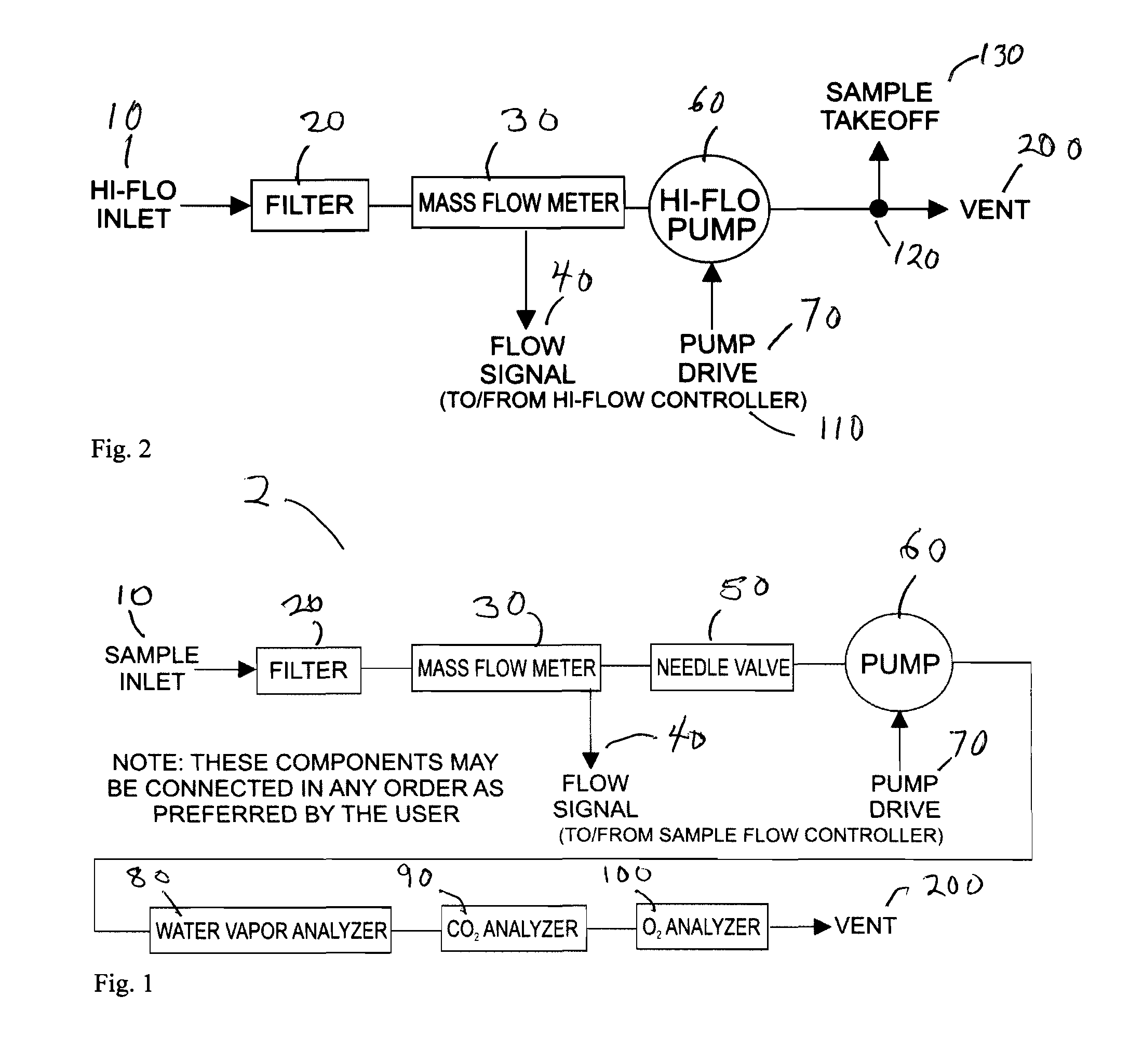
[0016] The inventive field apparatus satisfies not only the need for oxygen and carbon dioxide measurement in a single protected apparatus, dustproof and waterproof for travel, but also the need to further incorporate a water vapor analyzer, for immediate correction of water...


PUM


Abstract

A system for performing respirometry in the field that has the following: a) a sample inlet; b) a filter connected to the sample inlet and to a mass flow meter, to prevent the entry of particulate matter; c) a pump connected to the mass flow meter; d) a plurality of analyzers connected to the pump to maintain flow through the analyzers, the plurality of analyzers comprising at least i) an oxygen analyzer; ii) a carbon dioxide analyzer; iii) a barometric pressure measurement means, plumbed either to ambient pressure, pressure within the flow system, or to both; iv) a water vapor analyzer to measure relative humidity (RH) in the sampled air; and v) a temperature sensor near the water vapor analyzer; e) a data acquisition system that translates into digital form data from the plurality of analyzers; f) a data management system that incorporates data from the analyzers and performs calculations to at least determine percentages of oxygen and carbon dioxide corrected for water vapor pressure; g) a control system integrated into the apparatus to provide user control over at least some of the calculations; and h) a display for readouts of the plurality of analyzers and results of the calculations.

Description

RELATED APPLICATIONS [0001] This application claims the benefit of Provisional Application No. 60 / 822,072, filed Aug. 10, 2006.TECHNICAL FIELD [0002] This invention relates to measurements of concentrations of oxygen, carbon dioxide, temperature and several other parameters with an apparatus hardened for field use. BACKGROUND [0003] For field-portable work in aerial respirometry, several traditionally independent pieces of equipment were required. A pump provided motive force for air flow. A separate mass flow controller controlled STP-corrected air flow rate, which was subsampled by another pump and flow control system if required. An oxygen analyzer measured oxygen concentrations. A carbon dioxide analyzer measured carbon dioxide concentrations. A water vapor analyzer measured water vapor concentrations, and so forth. Additionally, a data acquisition system was required that communicated with a computer or retained raw data for later transfer to a computer. Often no final calculat...

Claims


Application Information

Patent Timeline
IPC IPC(8): A62B7/00
CPCG01N33/497
Inventor LIGHTON, JOHN R.B.
Owner SABLE SYST INT
Learn More