Bicycle frame with a counter-rotating four bar linkage system

Inactive Publication Date: 2008-03-06
LU DANIEL T F
View PDF11 Cites 65 Cited by
  • Summary
  • Abstract
  • Description
  • Claims
  • Application Information

AI Technical Summary

Benefits of technology

[0008]The primary objective of the present invention is to provide a bicycle frame with a counter-rotating four bar linkage system that can optimize the suspension efficiency o

Problems solved by technology

Accordingly, when the rider is pedaling heavily, the pedaling force of the rider is absorbed by the shock absorber (C) and the backward and downward movement of the VPP has a tendency to aggravate such interference between the rider and the rear frame section.
The backward and downward movement of VPP also has a tendency to aggravate such interference between the rider and the rear frame.
However, the position of the rear wheel axle moves in a backwardly curved tra

Method used


Image

  • Bicycle frame with a counter-rotating four bar linkage system
  • Bicycle frame with a counter-rotating four bar linkage system
  • Bicycle frame with a counter-rotating four bar linkage system

Examples


Embodiment Construction

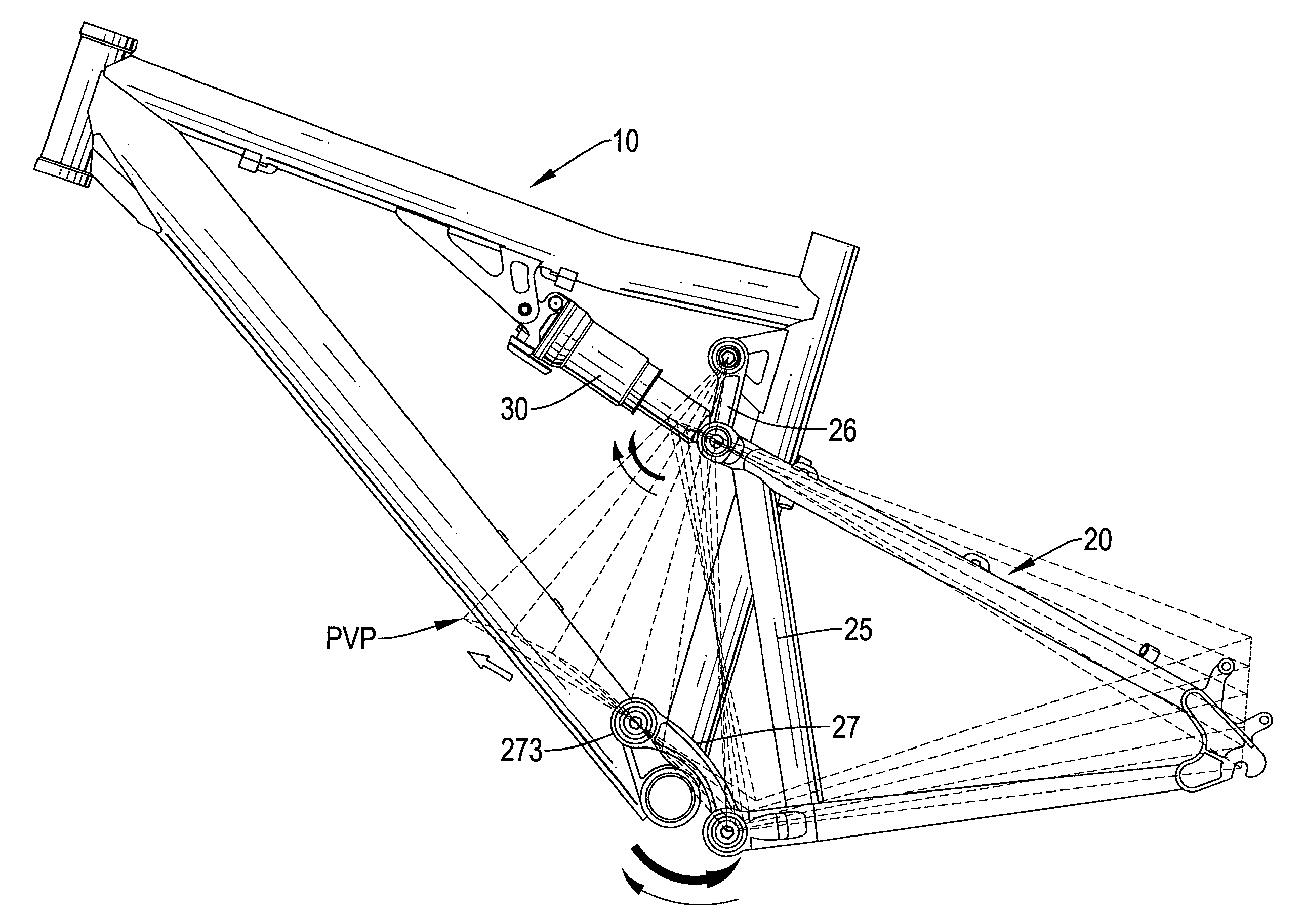
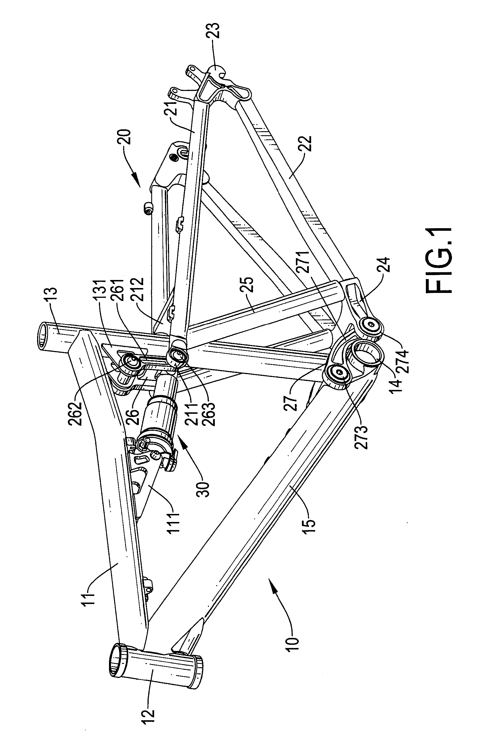
[0020]With reference to FIGS. 1, 2 and 3, a bicycle frame with a counter-rotating four bar linkage system in accordance with the present invention comprises a front frame section (10), a rear frame section (20) and a shock absorber (30).

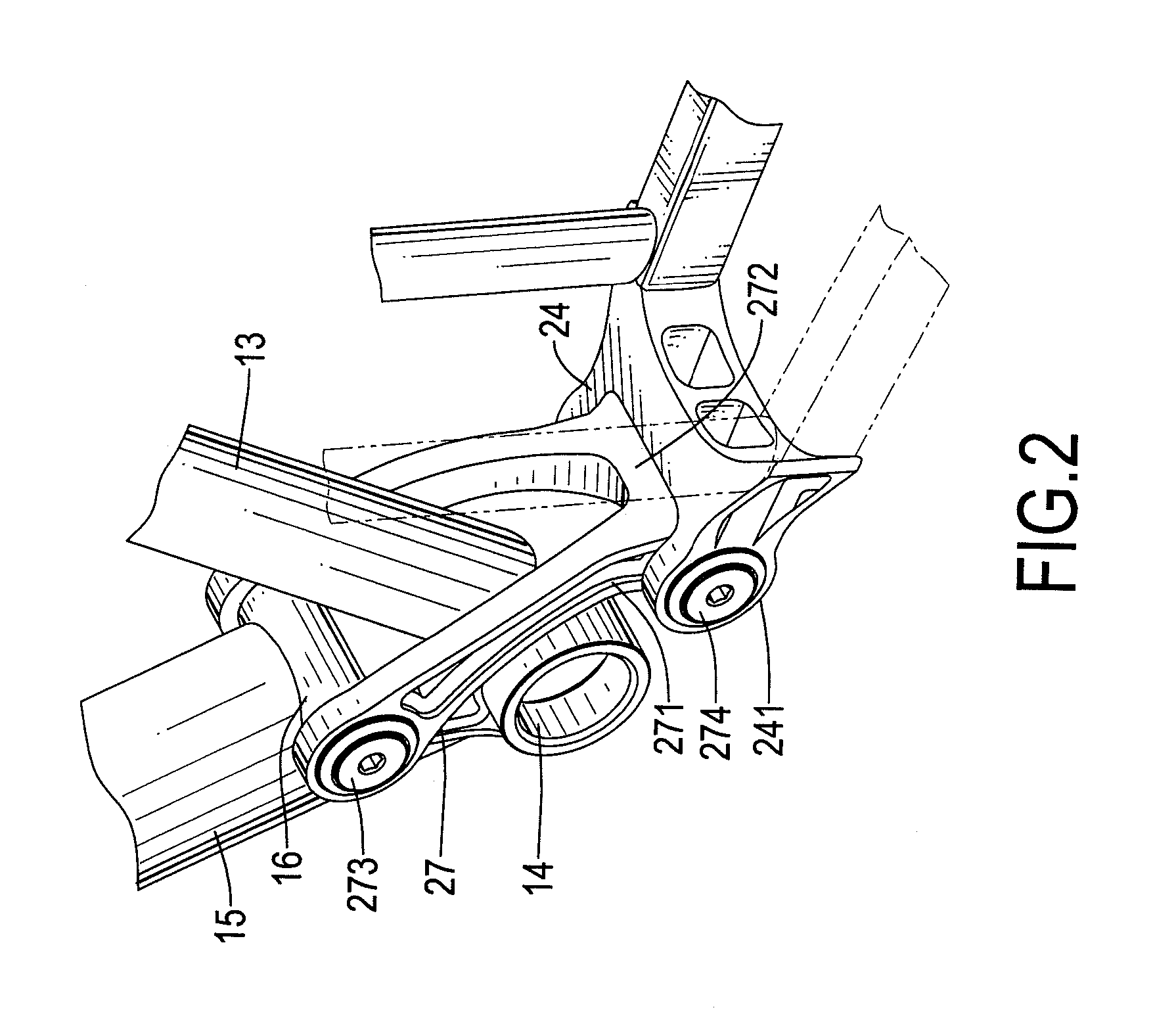
[0021]The front frame section (10) has a top tube (11), a head tube (12), a seat tube (13), a bottom bracket (14), a down tube (15) and a pivoting base (16). The top tube (11) is substantially horizontal and has a front end, a rear end, a middle segment and a mounting bracket (111). The mounting bracket (111) is mounted downwardly on the middle segment of the top tube (11) for connecting with the shock absorber (30). The head tube (12) is connected to the front end of the top tube (11) for mounting around a front fork of the bicycle. The seat tube (13) is connected to the rear end of the top tube (11) for mounting a saddle of the bicycle and has an upper end, a lower end and a mounting bracket (131). The mounting bracket (131) is mounted on the seat ...


PUM


Abstract

A bicycle frame with a counter-rotating four bar linkage system includes a front frame section, a rear frame section, and a shock absorber. The front frame section includes a top tube, a head tube, a seat tube, a bottom bracket, a down tube and a pivoting base formed on the down tube near the bottom bracket. The rear frame section is connected pivotally to the front frame section and has two seat stays, two chain stays, two dropouts, a connecting member, an upper linkage member, a lower linkage member and a parabolic virtual pivot (PVP). The PVP moves in a forwardly and upwardly parabolic trajectory and the dropouts of the rear frame section move in a nearly vertical trajectory when the rear frame section is pivoting.

Description

BACKGROUND OF THE INVENTION[0001]1. Field of Invention[0002]The present invention relates to a bicycle frame, and more particularly to a bicycle frame with a counter-rotating four bar linkage system that can optimize the suspension efficiency of the bicycle frame.[0003]2. Description of the Related Art[0004]With reference to FIG. 5, a conventional bicycle frame with a four bar linkage system comprises a front frame section (A), a rear frame section (B), an upper linkage member (D), a lower linkage member (E) and a shock absorber (C). The rear frame section (B) is mounted pivotally on the front frame (A) through the upper and lower linkage members (D, E). Both the upper and lower linkage members (D, E) have two pivots and an extension line defined by the pivots. The shock absorber (C) is mounted between the front frame section (A) and the upper linkage member (D). A virtual pivot point (VPP) is an intersection of the extension lines of the upper and lower linkage members (D, E). Beca...

Claims


Application Information

Patent Timeline
IPC IPC(8): B62K5/00
CPCB62K25/286
Inventor LU, DANIEL T.F.
Owner LU DANIEL T F
Why Eureka
Try Eureka