Headphone

a headphone and headphone technology, applied in the field of headphone, can solve the problems of increasing the number of components, troublesome first method, and disproportionately large portion that is mounted to the head

Inactive Publication Date: 2008-03-06
SONY CORP
View PDF3 Cites 101 Cited by
  • Summary
  • Abstract
  • Description
  • Claims
  • Application Information

AI Technical Summary

Benefits of technology

[0018]It is further desirable to provide a headphone in which an excessive portion of a cord is compactly held without being exposed to the outside, when a housing is adjusted so as to approach a headband.
[0022]According to another embodiment of the present invention, there is provided a headphone including a headband and a left housing and a right housing. The left housing and the right housing are mounted to respective ends of the headband through respective hangers. Each housing accommodates a drive unit. Rod sliders are mounted to the respective hangers, and are slidably supported at slidably supporting portions at the respective ends of the headband. A cord, disposed between the left and right housings and used to pass drive electric current to the drive unit in one of the housings, is spirally wound upon outer peripheral surfaces of the rod sliders so that the cord is capable of being stretched and compressed.
[0025]According to the above-described form, the coiled cord is disposed in the tubular sliders, and follows the sliding of the sliders. Therefore, the cord is compactly disposed so that it is no longer exposed to the outside. As a result, the headphone also has a structure that prevents breakage of the cord caused by external shock. In the structure in which the coiled cord is wound upon one of the rod sliders, the cord is exposed to the outside, but the position of the cord is restricted by the slider, and the cord follows the sliding of the slider. Therefore, it is possible to more reliably prevent the cord from breaking, and to make the headphone structure compact.

Problems solved by technology

A user may feel that the first method is troublesome and causes discomfort because two cords, that is, the left and right cords, are drawn out to a neck.
Therefore, the headband becomes large, resulting in the problem that a portion that is mounted to a head becomes disproportionately large.
In addition, since the portion that is mounted to the head includes two components, the headband and a suspender constituting the head cushion, the number of components is increased, thereby increasing weight.

Method used


Image

  • Headphone
  • Headphone
  • Headphone

Examples


Embodiment Construction

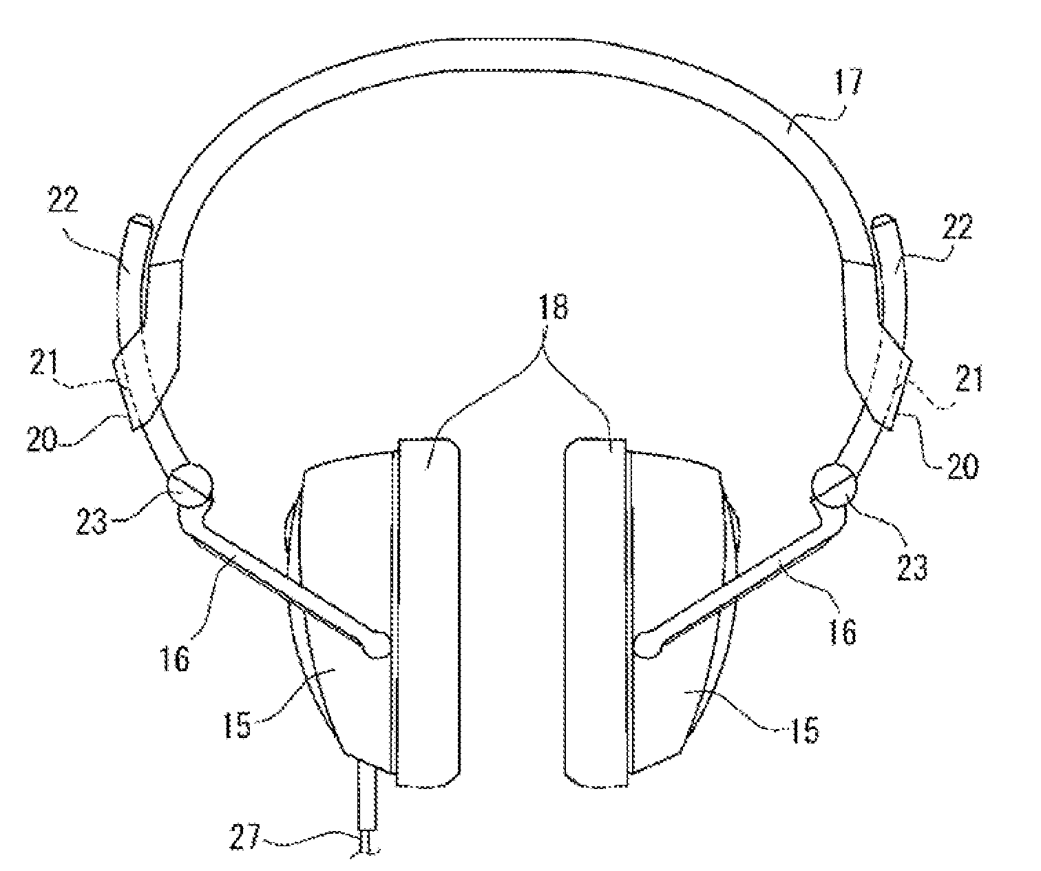
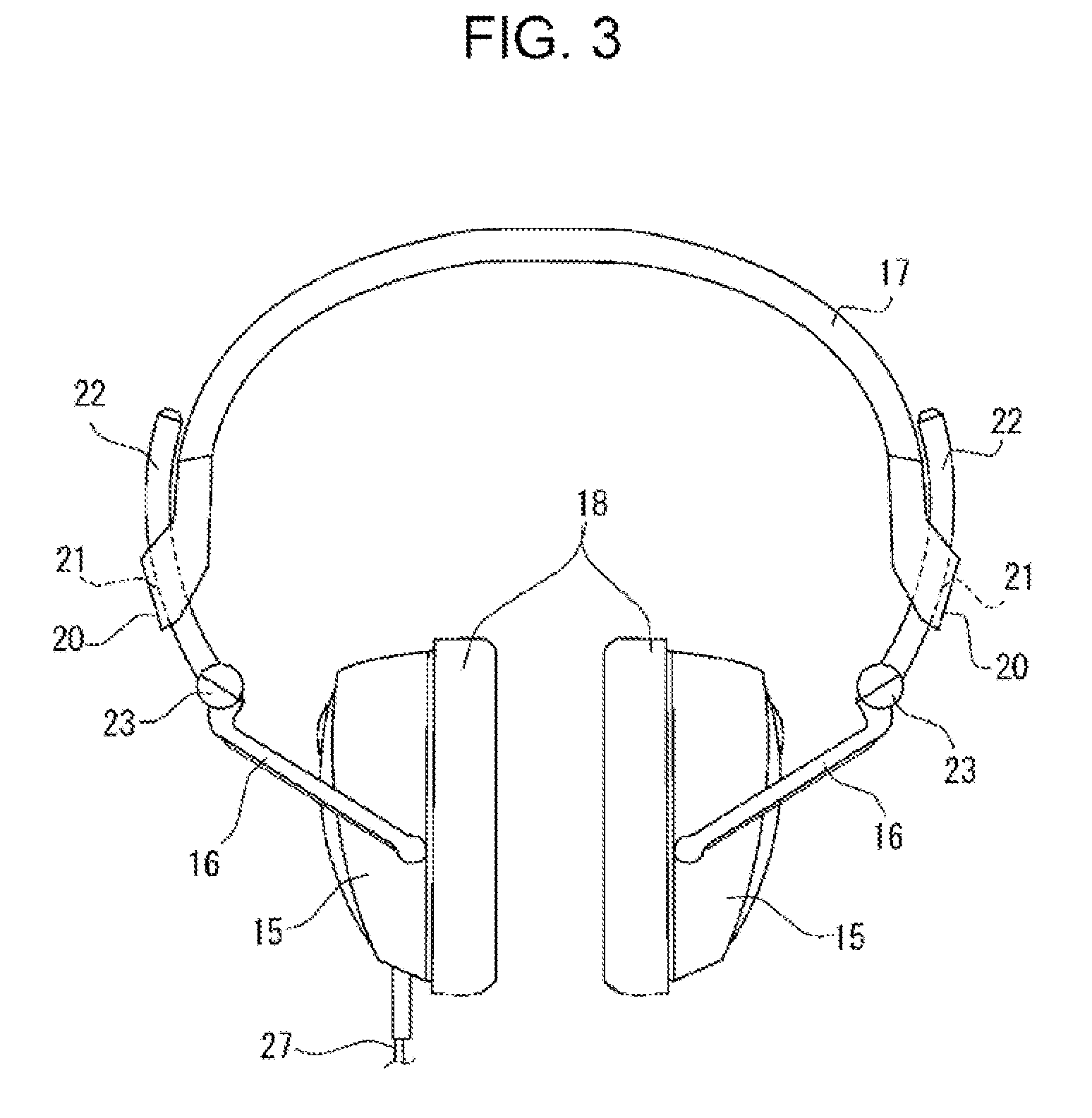
[0047]The invention of the application will hereunder be described with reference to illustrated embodiments. First, a first embodiment will be described. FIGS. 3 and 4 show an entire structure of a headphone according to the first embodiment. The headphone includes a pair of left and right housings 15. Baffle plates are mounted in the housings 15 so as to close the entrances of the housings 15. Drive units including small speakers are mounted to inner sides of the respective baffle plates. When signal electric current passes through voice coils of the drive units, sound is reproduced on the basis of the same principle as that of a speaker. The housings 15 are rotatably connected to respective hangers 16, and are mounted to a headband 17 through the respective hangers 16. Ear pads 18 are mounted to inner peripheral portions of the respective housings 15.

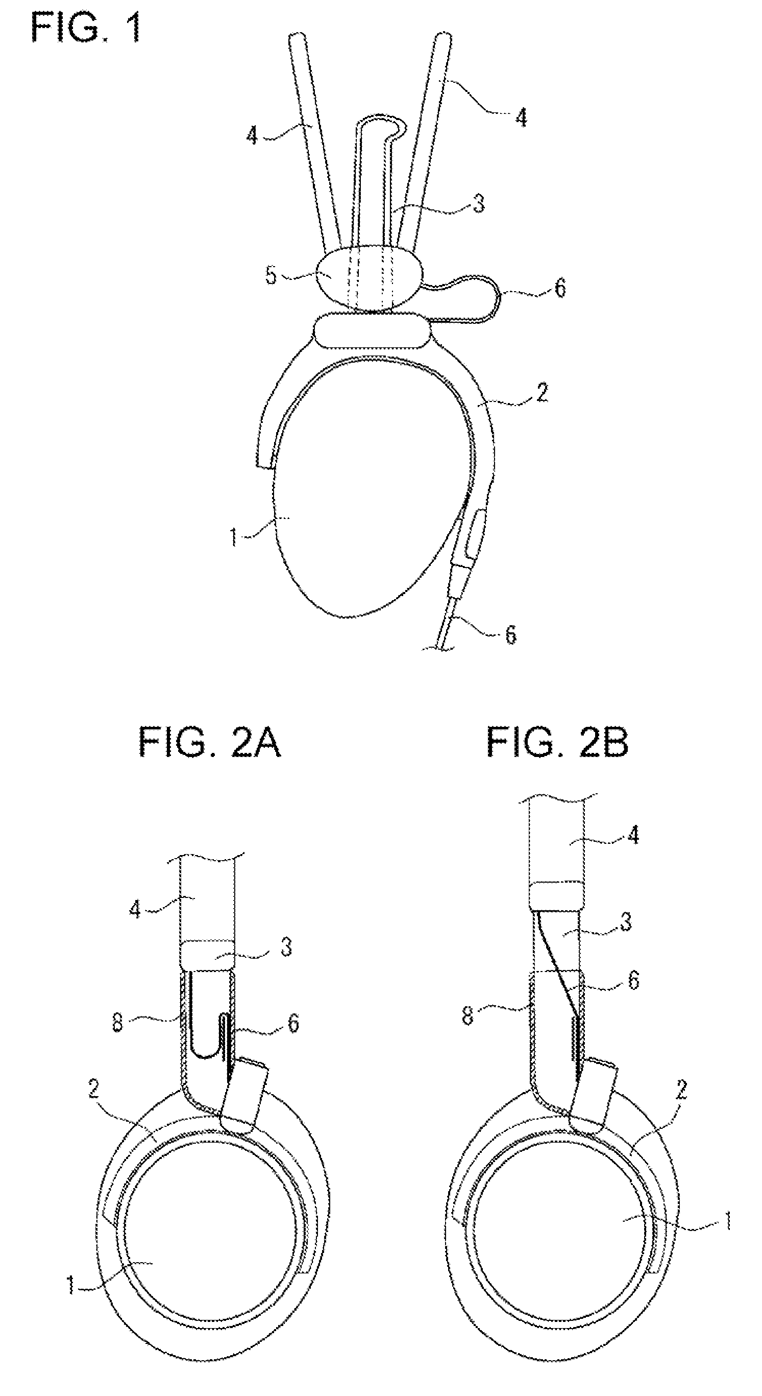
[0048]Here, adjusting mechanisms for adjusting the positions of the housings 15 and the headband 17 relative to each other are prov...


PUM


Abstract

A headphone includes a headband and a left housing and a right housing. The left housing and the right housing are mounted to respective ends of the headband through respective hangers. Each housing accommodates a drive unit. Sliders including hollow cylindrical members are mounted to the respective hangers, and are slidably supported at slidably supporting portions at the respective ends of the headband. A cord, disposed between the left and right housings and used to pass drive electric current to the drive unit in one of the housings, is spirally accommodated in the hollow cylindrical members making up the respective sliders so that the cord is capable of being stretched and compressed.

Description

CROSS REFERENCES TO RELATED APPLICATIONS[0001]The present invention contains subject matter related to Japanese Patent Application JP 2006-241703 filed in the Japanese Patent Office on Sep. 6, 2007, the entire contents of which are incorporated herein by reference.BACKGROUND OF THE INVENTION[0002]1. Field of the Invention[0003]The present invention relates to a headphone, and, more particularly, to a headphone having left and right housings, which accommodate drive units, mounted at respective ends of a headband through hangers.[0004]2. Description of the Related Art[0005]To, for example, enjoy music while preventing sound from leaking to the outside, a headphone has hitherto been widely used. In general, a headphone has a structure in which left and right housings are mounted to respective ends of a headband through hangers. In the housings, drive units including small speakers are disposed. Therefore, by passing electric current through voice coils of the drive units, sound is rep...

Claims


Application Information

Patent Timeline
Patent Type & Authority Applications(United States)
IPC IPC(8): H04R25/00
CPCH04R1/1033H04R5/0335H04R1/1066
Inventor FUJIWARA, KEITAROTSUNODA, NAOTAKAOOSATO, YUUSUKE
Owner SONY CORP
Why Eureka
Try Eureka