Bearing positioning structure for motor
a technology of bearing positioning and motor, which is applied in the direction of bearing unit rigid support, record information storage, instruments, etc., can solve the problems of unreliable bearing positioning, and achieve the effect of improving assembly reliability
- Summary
- Abstract
- Description
- Claims
- Application Information
AI Technical Summary
Benefits of technology
Problems solved by technology
Method used
Image
Examples
first embodiment
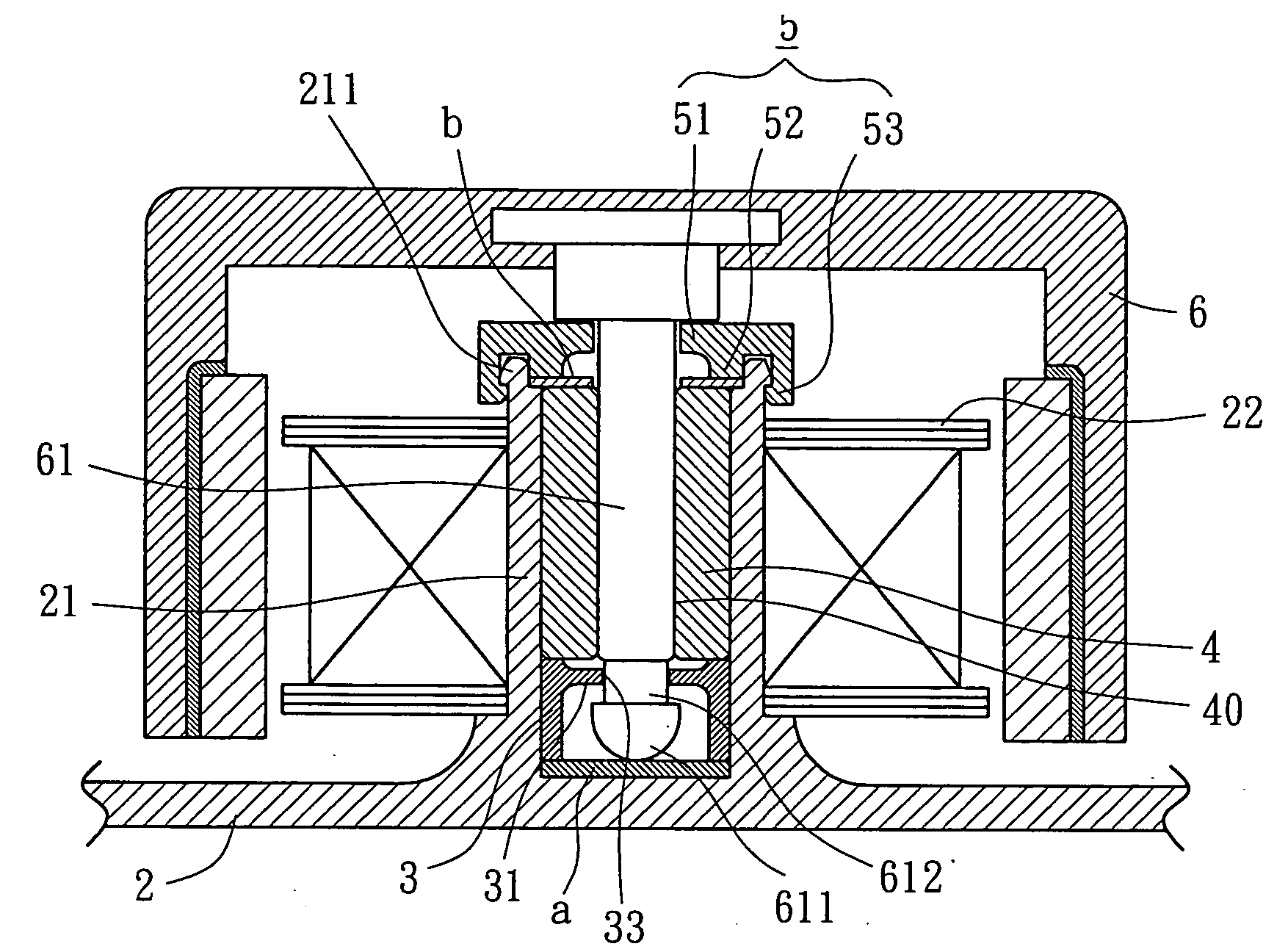
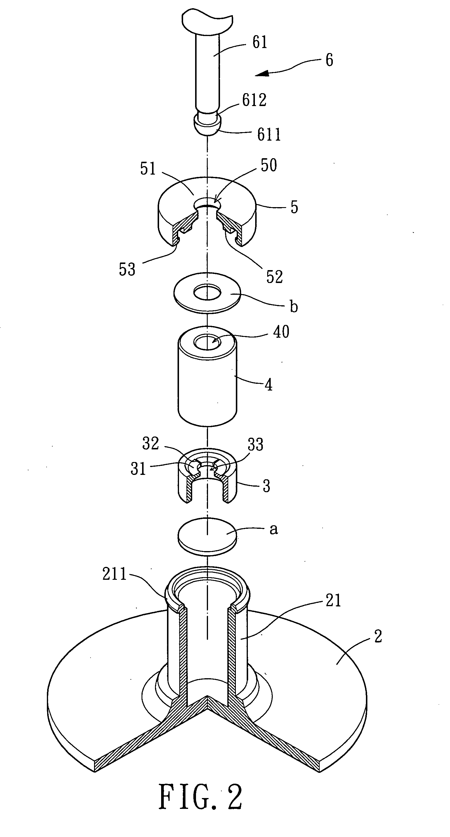
[0034]Referring to FIGS. 2 and 3, a bearing positioning structure in accordance with the present invention comprises a base 2, a restraining member 3, a bearing 4, a positioning member 5, and a rotor 6. Mounted to the base 2 is an axial tube 21 and a stator 22, wherein the axial tube 21 may be assembled to or integrally formed with the base 2 for receiving motor elements including the restraining member 3, the bearing 4, and the positioning member 5. The stator 22 may be of radial winding type or axial winding type. The restraining member 3 restrains axial movement of a shaft 61 of the rotor 6 relative to the axial tube 21. The bearing 4 may be an oily bearing, a ball bearing, a fluid dynamic bearing, etc. The shaft 61 is rotatably extended through the bearing 4. The positioning member 5 is engaged with the axial tube 21 for reliably positioning the bearing 4 in the axial tube 21.
[0035]Still referring to FIGS. 2 and 3, the axial tube 21 of the first embodiment in accordance with the...
third embodiment
[0043]Still referring to FIGS. 5 and 6, the stator 22 of the third embodiment is engaged with the axial tube 21 by providing a second coupling section 222 on a bottom portion of the stator 22 for engaging with an engaging portion 212 of the axial tube 21. Hence, the stator 22 is reliably fixed to the axial tube 21. Preferably, the engaging portion 212 is formed on an outer circumference of the axial tube 21 and corresponding to the second coupling section 222. Preferably, the first and second coupling sections 221 and 222 are hooks.
[0044]Still referring to FIGS. 5 and 6, in assembly of the motor elements of the third embodiment, the restraining member 3, the bearing 4, and the positioning member 5 are mounted into the axial tube 21 in sequence. Next, the first coupling section 221 and the second coupling section 222 of the stator 22 are respectively engaged with the coupling portion 53 of the positioning member 5 and the engaging portion 212 of the axial tube 21 such that the stator...
PUM
 Abstract
Description
Claims
Application Information
 - R&D
- Intellectual Property
- Life Sciences
- Materials
- Tech Scout
- Unparalleled Data Quality
- Higher Quality Content
- 60% Fewer Hallucinations
Browse by: Latest US Patents, China's latest patents, Technical Efficacy Thesaurus, Application Domain, Technology Topic, Popular Technical Reports.
© 2025 PatSnap. All rights reserved.Legal|Privacy policy|Modern Slavery Act Transparency Statement|Sitemap|About US| Contact US: help@patsnap.com


