Spinal fusion implant

a fusion implant and spine technology, applied in the field of spine fusion implants, can solve the problems of collateral tissue damage, difficult to extend the range of fusion technique beyond the range of two to three vertebrae, and increasing the distance from the screw head

Inactive Publication Date: 2008-03-06
MICRODEXTERITY SYST
View PDF27 Cites 63 Cited by
  • Summary
  • Abstract
  • Description
  • Claims
  • Application Information

AI Technical Summary

Benefits of technology

[0004]According to the present invention, the long continuous rod used in conventional spinal fusion procedures is replaced with short segments that can be inserted through the same types of access ports used to install the pedicle screws. Each rod segment has the ability to reach from one pedicle screw to the next. The pedicle screw is used to clamp on to the rod segments. The rod segments can take a variety of shapes from simple cylindrical short rods to sophisticated coined and forged shapes with special heads and features to lock one rod segment to the next.

Problems solved by technology

It becomes quite difficult to extend this technique beyond the range of two to three vertebrae.
If the arc of the tie rod is made larger, then the insertion point becomes increasingly further away from the screw heads and collateral tissue damage occurs.

Method used


Image

  • Spinal fusion implant
  • Spinal fusion implant
  • Spinal fusion implant

Examples


Embodiment Construction

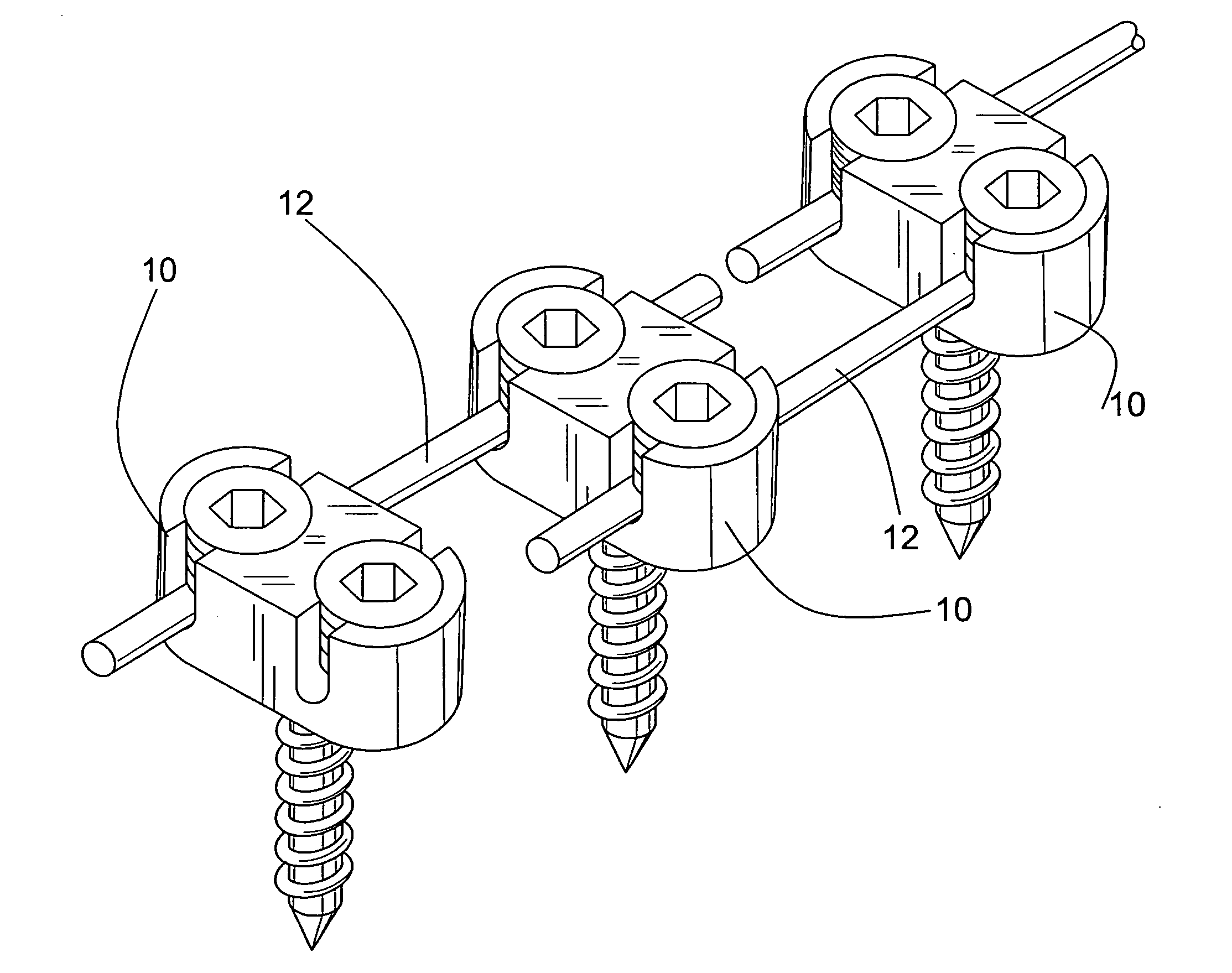
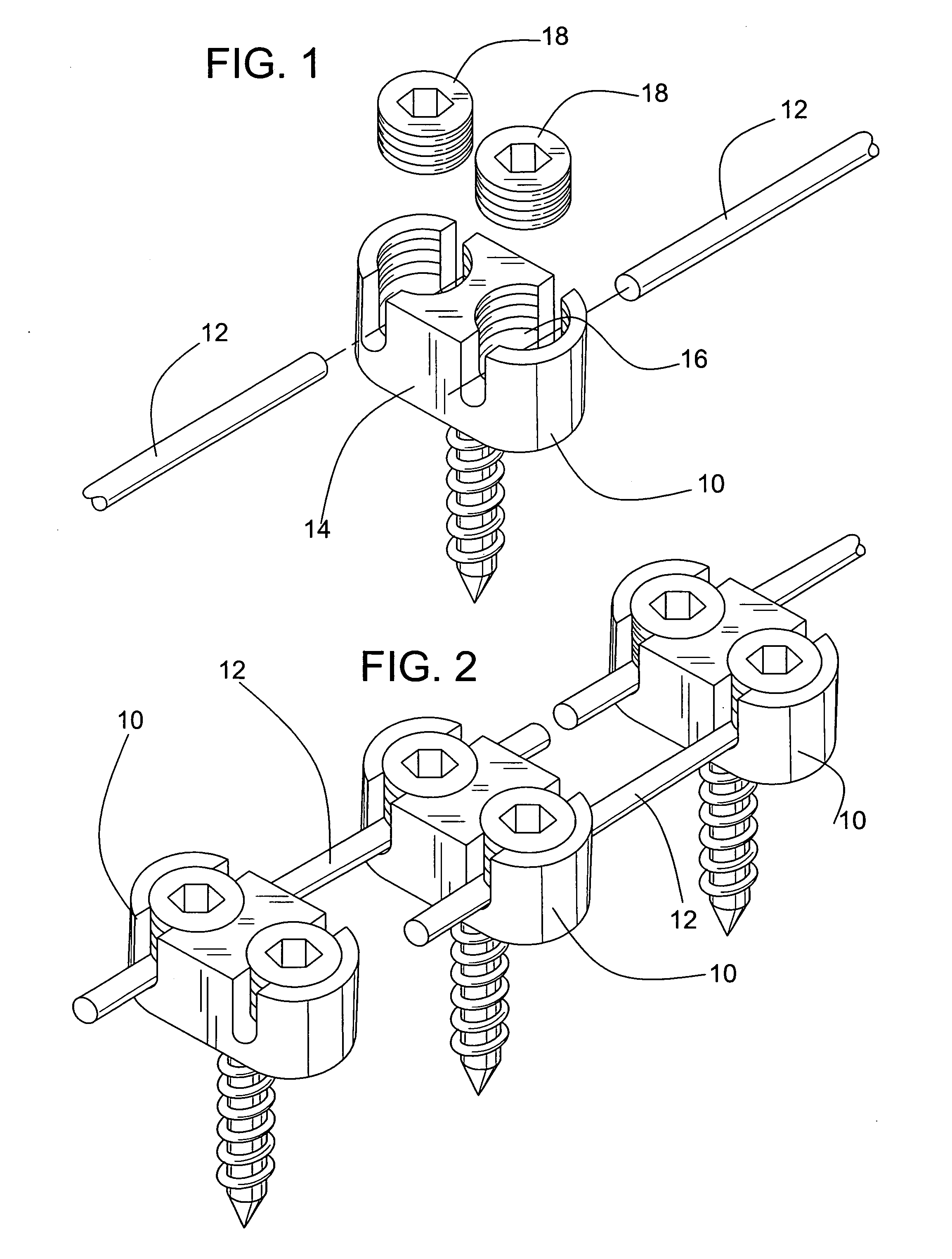
[0026]Referring to FIG. 1 of the drawings there is shown an exemplary embodiment of a spinal fusion system according to the present invention. The system of FIG. 1 includes one or more pedicle screws 10 and one or more links or rod segments 12. Each pedicle screw includes a head portion and a depending shank portion that is used to secure the pedicle screw to bone. The rod segments 12 can take any desired shape or configuration sufficient to reach from one pedicle screw to the next, such as, for example, cylindrical or flat rods, bars or wires. Advantageously, the rod segment 12 of FIG. 1 has a very simple, substantially straight configuration.

[0027]Each of the pedicle screws 10 used with the rod has a generally oval, figure-eight configured head 14 that defines two separate slotted recesses 16 each of which can receive a rod segment 12. To this end, each of the slotted recesses 16 has opposing notches in the sidewall of the recess through which a rod segment can be inserted. Additi...


PUM


Abstract

A spinal fusion implant system and a method of using the spinal fusion implant system are provided. The spinal fusion implant system includes a plurality of links with each link having a pair of opposing end portions. The spinal fusion implant system also includes a plurality of pedicle screws. Each pedicle screw has a head and a depending shank for fixing the pedicle screw to a bone. The head has a slotted recess configured to receive one end portion of at least two different links or two slotted recesses each of which is configured to receive an end portion of one of the links. Each recess has an associated set screw for clamping the end portions of the respective links in the recess.

Description

FIELD OF THE INVENTION[0001]The present invention relates to implants that can be used to perform spinal fusions and other procedures where vertebrae are linked together by a rod that is routed through the heads of pedicle screws.BACKGROUND OF THE INVENTION[0002]Spinal fusion is a well-developed open surgical procedure in which vertebrae are linked together by a rod that is routed through the heads of pedicle screws that are attached to each vertebra. In particular, the pedicle screws have a slot in the head to accommodate a rod that passes from one screw to the other. The rod is secured to each pedicle screw with a second set screw component. This set screw binds to the rod and holds the vertebrae in a specific orientation and alignment.[0003]Recently, devices have been developed that can perform these spinal fusion procedures with less invasion of the tissue. Such devices only require ports to place the screws and a “needle puncture” to insert a tie rod through the heads of the pe...

Claims


Application Information

Patent Timeline
Patent Type & Authority Applications(United States)
IPC IPC(8): A61F2/30
CPCA61B17/7005A61B17/705A61B17/7007
Inventor STUART, J. MICHAEL
Owner MICRODEXTERITY SYST
Why Eureka
Try Eureka