Grip for a handgun

a technology for handguns and grips, applied in the direction of breech mechanisms, weapon components, weapon assembly/disassembly, etc., can solve the problem of not being able to adapt the grip to the different specifications of weapons straight away, and achieve the effect of simple and cost-effective adaptation

Inactive Publication Date: 2008-03-13
T SWISS ARMS TECH
View PDF13 Cites 48 Cited by
  • Summary
  • Abstract
  • Description
  • Claims
  • Application Information

AI Technical Summary

Benefits of technology

[0003] The objective of the invention is to create a grip that enables a simple

Problems solved by technology

For this known weapon, adapting the grip to differing specifications of the weapon is not possible straight away, since the plas

Method used


Image

  • Grip for a handgun
  • Grip for a handgun
  • Grip for a handgun

Examples


Embodiment Construction

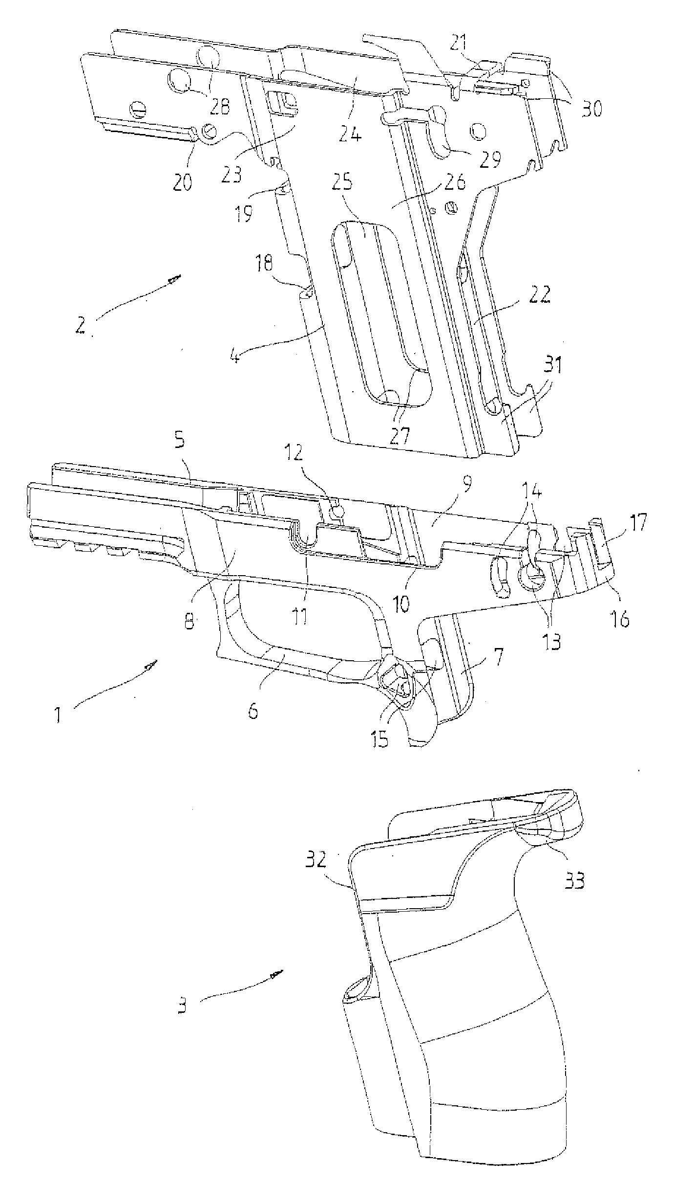
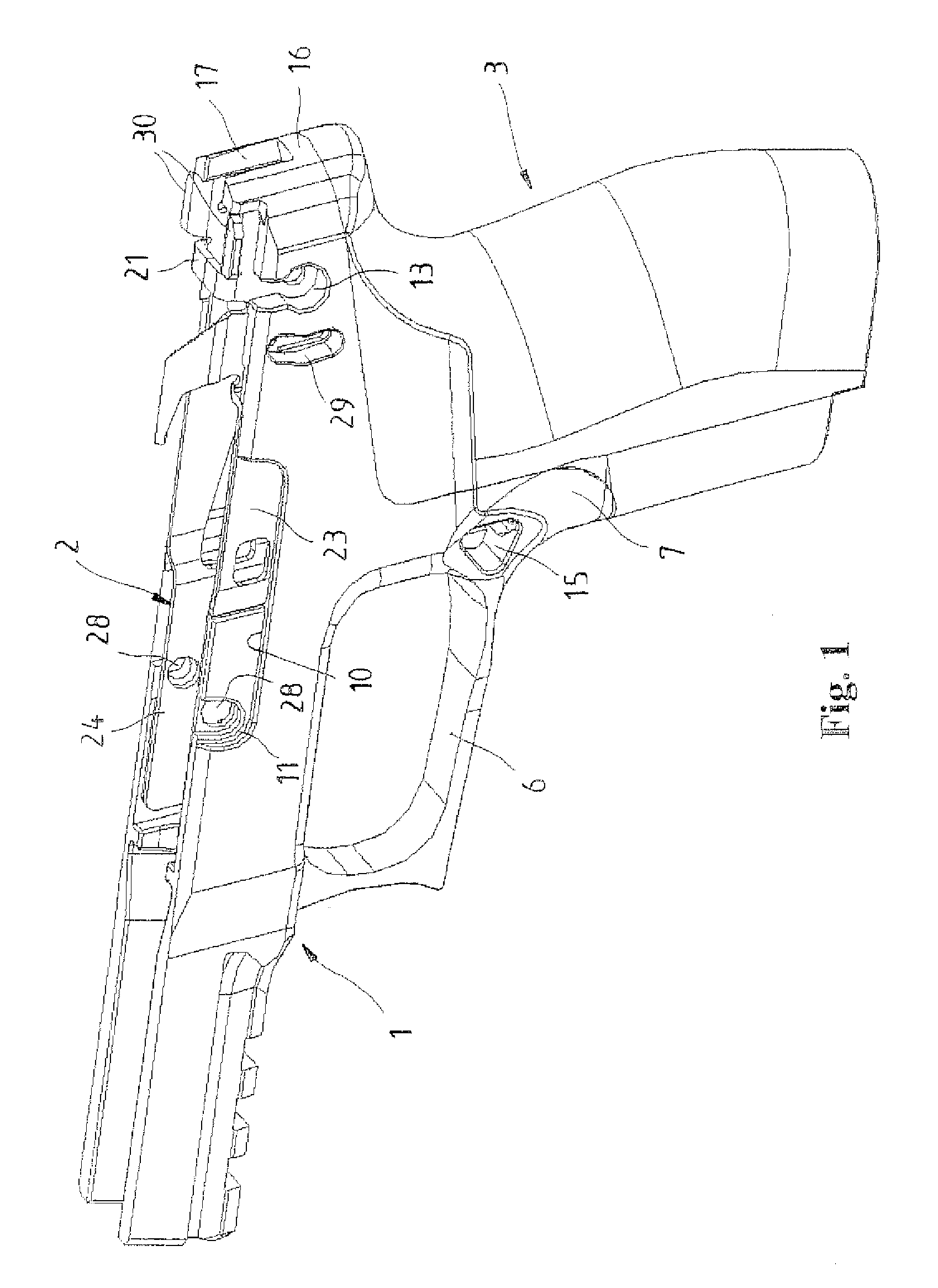
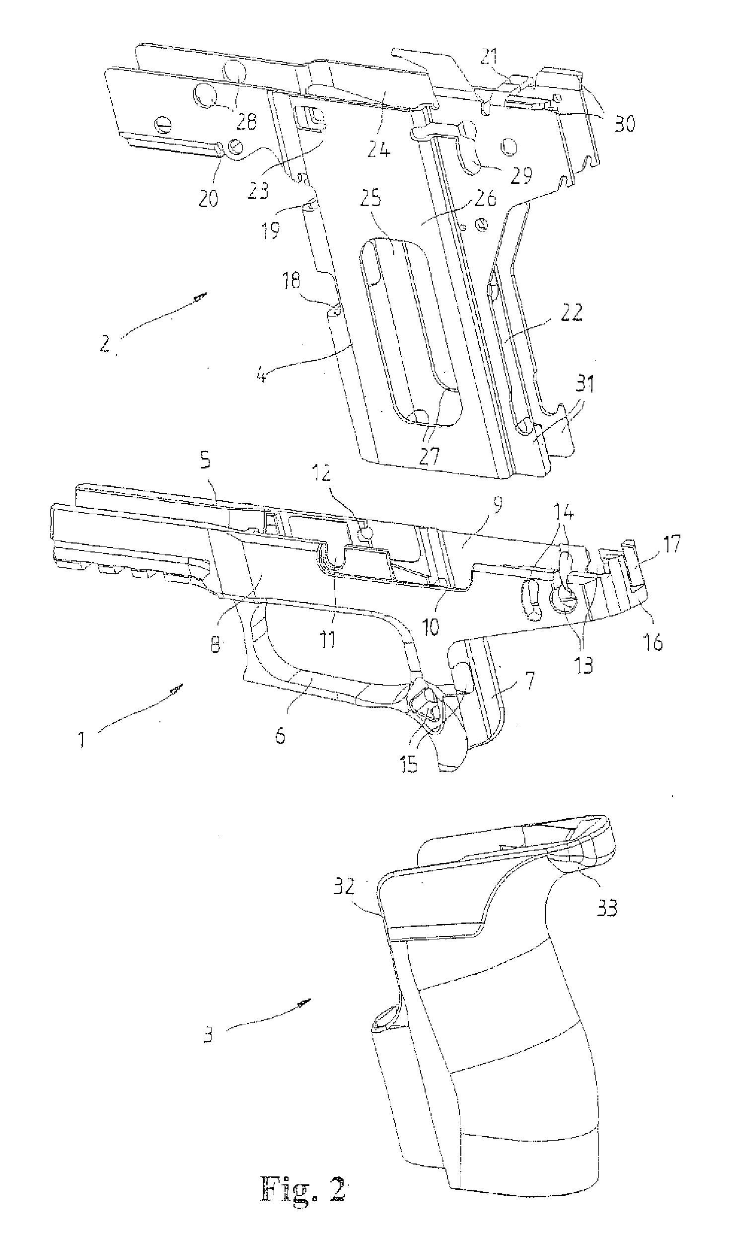
[0014] The grip of a pistol depicted diagrammatically in FIGS. 1 and 2 is composed of a grip module (1), a carrier element (2) insertable in said grip module (1), and a grip shell module (3) capable of being slipped onto the carrier element (2). As emerges from FIG. 2 in particular, a downward extending magazine shaft (4) is formed on the carrier element (2) that is insertable in the grip module (1).

[0015] The grip module (1), preferably manufactured as an injection-molded part of plastic, comprises simply an upper retainer part (5) in the form of a frame, on the underside of which is molded a trigger guard (6) and a front cover (7) in the shape of a half shell for the upper part of the magazine shaft (4). The action or slide of the handgun, not represented here, is slidably arranged on the retainer part (5). Various openings or recesses or hollows for different control elements or functional elements are provided in the two sidewalls (8, 9) of the upper retainer part (5). Thus a l...


PUM


Abstract

The invention relates to a grip for a handgun, in particular a pistol, having a grip module (1) made of plastic and a metal carrier element (2) that is insertable into said grip module (1). In order to enable a simple and cost-effective adaptation to the widest variety of demands of the marksman, a magazine shaft (4), projecting downward from the grip module (1) and onto which is slipped a grip shell module (3), is formed as a part of the carrier element (2).

Description

FIELD OF THE INVENTION [0001] The invention relates to a grip for a handgun, in particular a pistol. BACKGROUND OF THE INVENTION [0002] A grip of this type is known from EP 0 979 986 A2. There, a single multi-function part made of metal is inserted in a removable way in a housing made of plastic. However, the multi-function part serves here only for guidance and support of the elements of the trigger mechanism and contains the guides for the barrel slide, which is slidable on the grip. The magazine shaft is formed in a plastic housing designed as a single-piece. For this known weapon, adapting the grip to differing specifications of the weapon is not possible straight away, since the plastic housing is of integral design, and in the event of potential changes or adaptations must always be replaced in its entirety. SUMMARY OF THE INVENTION [0003] The objective of the invention is to create a grip that enables a simple and cost-effective adaptation to the widest variety of demands of ...

Claims


Application Information

Patent Timeline
IPC IPC(8): F41C23/16
CPCF41A3/66F41C23/10F41A11/02
Inventor THOMELE, ADRIANMETZGER, THOMASHOFS, STEFAN
Owner T SWISS ARMS TECH
Why Eureka
Try Eureka