
Vehicle compartment locking apparatus

a technology for vehicle compartments and locking apparatuses, which is applied in the direction of anti-theft devices, mechanical controls, transportation and packaging, etc., can solve the problems of compromising the security of the vehicle or items within the vehicle, major problems for owners, and theft of items inside the vehicle, so as to achieve convenient locking and opening, the effect of convenient locking

Inactive Publication Date: 2008-03-13
HARVEY STEVEN M
View PDF1 Cites 11 Cited by
  • Summary
  • Abstract
  • Description
  • Claims
  • Application Information

AI Technical Summary

Benefits of technology

"The invention provides a better system for locking and opening various vehicle security systems. It has specific features and advantages that make it more convenient and efficient. The patent text allows for easy modification and design of other structures that achieve the same purposes as the invention."

Problems solved by technology

Theft and / or unauthorized use of vehicles and theft of items inside vehicles are a major problem for the owners.
While many security measures, such as locks or alarms, are well known in the prior art, most are somewhat inconvenient for the owner or operator of the vehicle.
This convenience will often lead an operator to choose to avoid using the vehicle security measure, thus compromising the security of the vehicle or items within the vehicle.
It is time consuming, especially when a vehicle has a plurality of compartments, to move to each door and lock or unlock it.
It can be difficult and expensive to retrofit existing trucks.
Further, prior art electrically operated locking systems which open multiple locks on multiple compartments simultaneously produce a very high amperage spike when the locks are operated.
This can put a significant strain on a vehicle's electrical system and can require heavy-duty wiring and fuses.
This prior art actuator, however, suffers from a number of shortcomings.
After-market installation typically requires extensive wiring and cutting holes in the vehicle body.
Further, electrical locking systems are undesirable for situations such as marine use where the system must be waterproof or for situations requiring explosion-proof equipment.
Finally, prior art electrically operated locking systems which open multiple locks on multiple compartments simultaneously produce a very high amperage spike when the locks are operated.
This can put a significant strain on a vehicle's electrical system and can require heavy-duty wiring and fuses.

Method used


Image

  • Vehicle compartment locking apparatus
  • Vehicle compartment locking apparatus
  • Vehicle compartment locking apparatus

Examples


Embodiment Construction

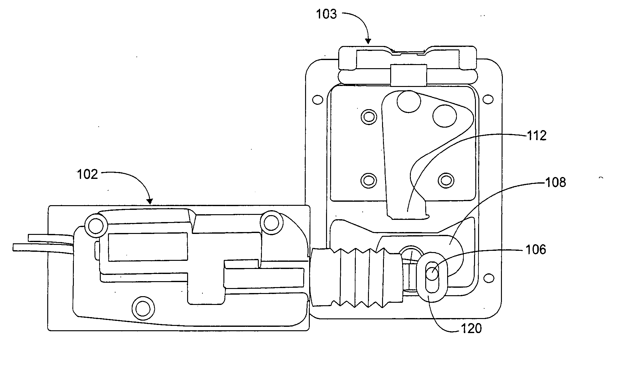
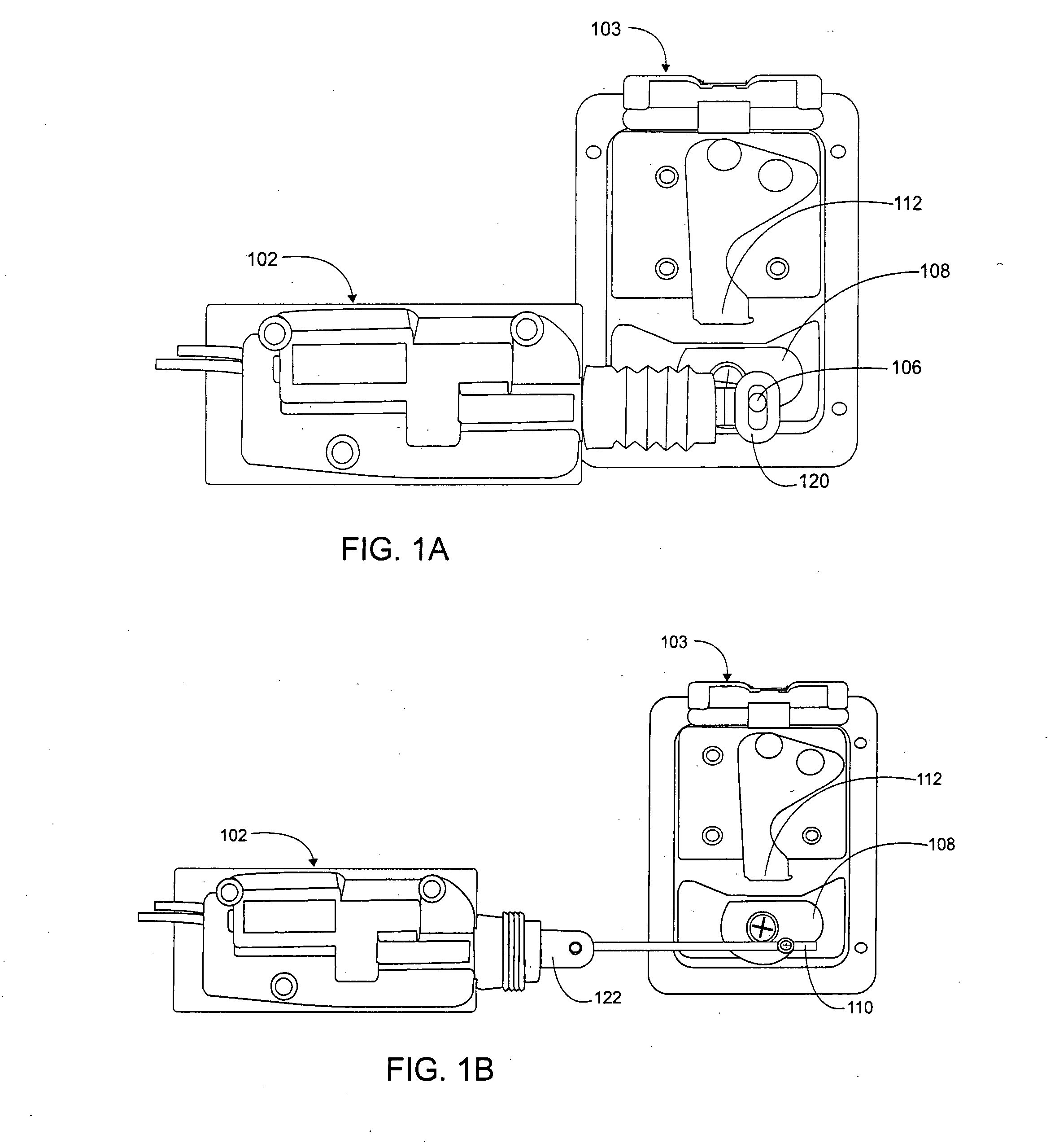
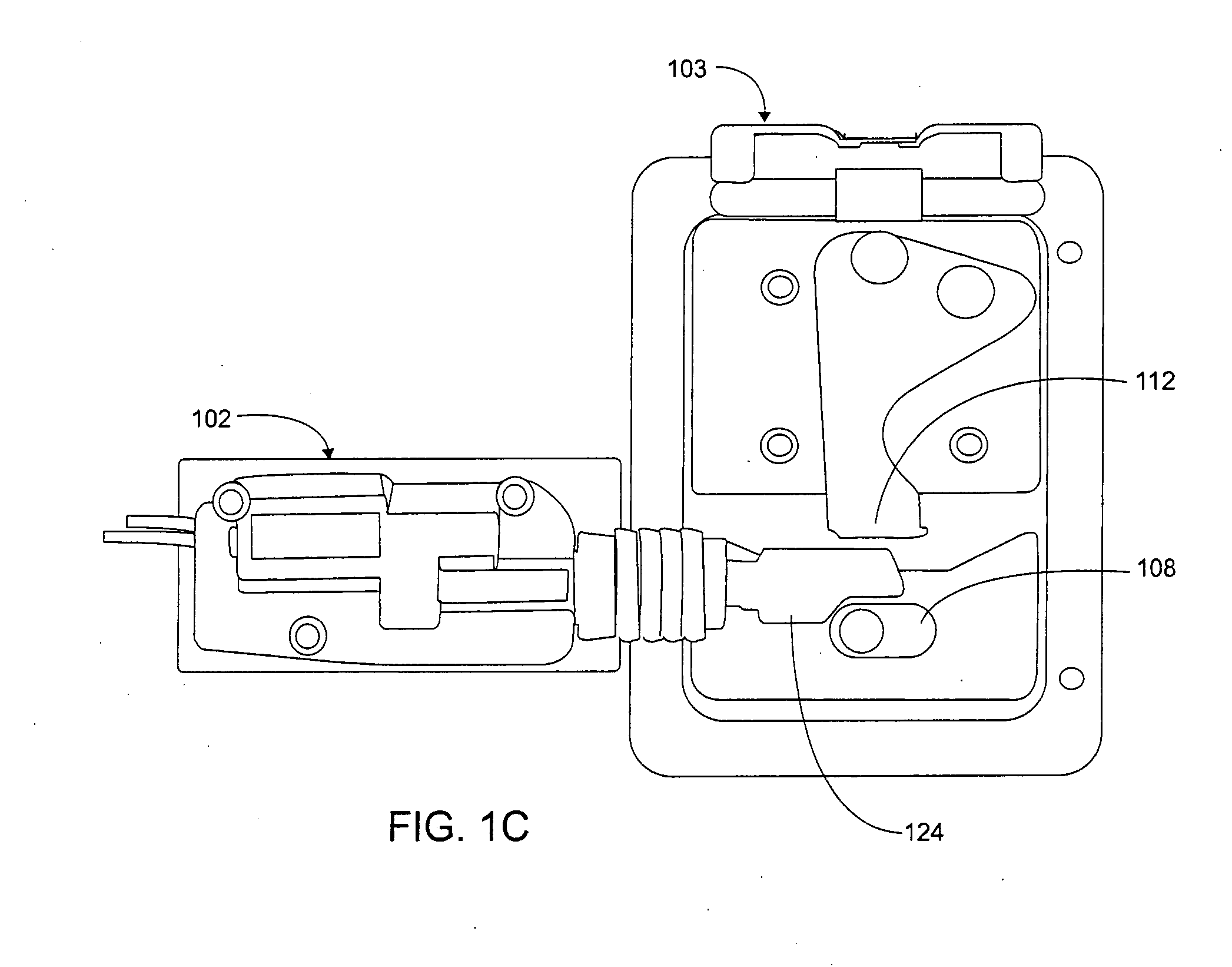
[0022] In one preferred embodiment of the present invention, an improved actuator is used to operate one or more locks on a vehicle. Several different actuator nosepieces can be used. For example, FIG. 1A shows an actuator 102 with a nosepiece 120 with a round head that attaches directly to a pin or bolt 106 on a lock cam 108. FIG. 1B shows an actuator nosepiece 122 with a small hole in the nosepiece head suitable for attaching to an extension rod 110, which in turn attaches to a cam 108. FIG. 1C shows an actuator nosepiece 124 that is shaped so that it pushes between the bolt 112 and the cam 108. In the prior art, actuators were manufactured and sold with a particular nosepiece.

[0023] According to the present invention, however, a key and slot assembly, shown in FIG. 2, allows the nosepieces to be easily replaced, either because the original has been damaged or because a different type of nosepiece is required. A key slot assembly 130 is located at the end of piston 310 as shown i...


PUM


Abstract

An improved actuator used to operate one or more locks on a vehicle. Preferred embodiments of the present invention are configured to lock and unlock multiple locks sequentially rather than simultaneously, allowing for the use of smaller and less expensive motors. Actuator nosepieces can also be changed out allowing the actuators to be easily used with different kinds of locking mechanisms. The actuating member is locked and unlocked by way of a compression spring and plunger assembly that is more robust than a torsion spring as in prior art.

Description

[0001] This application claims priority from U.S. Provisional App. No. 60 / 817,930 filed Jun. 30, 2006, and from U.S. Provisional App. No. 60 / 855,858 filed Nov. 1, 2006, both of which are hereby incorporated by reference.TECHNICAL FIELD OF THE INVENTION [0002] The invention relates to vehicle security devices, more particularly to electrical and pneumatic vehicle compartment locks. BACKGROUND AND SUMMARY OF THE INVENTION [0003] Theft and / or unauthorized use of vehicles and theft of items inside vehicles are a major problem for the owners. While many security measures, such as locks or alarms, are well known in the prior art, most are somewhat inconvenient for the owner or operator of the vehicle. This convenience will often lead an operator to choose to avoid using the vehicle security measure, thus compromising the security of the vehicle or items within the vehicle. [0004] For example, multiple storage compartments are built into a variety of vehicles such as rescue emergency units...

Claims


Application Information

Patent Timeline
Patent Type & Authority Applications(United States)
IPC IPC(8): E05B65/12B60R25/00E05B47/00
CPCE05B15/0053E05B77/48E05B81/34E05B81/25E05B81/06Y10T70/5889Y10T70/625
Inventor HARVEY, STEVEN M.
Owner HARVEY STEVEN M
Learn More