Automatic document feeder and image forming apparatus having the same

a document feeder and image forming technology, applied in the field of automatic document feeder of an image forming apparatus, can solve the problems of limiting the printing efficiency of duplex printing mode, low printing efficiency in duplex printing mode, etc., and achieve the effect of reducing the document admission interval and improving the duplex scanning or printing efficiency

Active Publication Date: 2008-03-13
HEWLETT PACKARD DEV CO LP
View PDF15 Cites 10 Cited by
  • Summary
  • Abstract
  • Description
  • Claims
  • Application Information

AI Technical Summary

Benefits of technology

[0012]The present general inventive concept provides an automatic document feeder to scan a document and collate and discharge the scanned document having both surfaces scanned, thereby reducing a document admission interval in a duplex scanning or printing mode and thus improving a duplex scanning or printing efficiency in the duplex scanning, or printing mode.
[0013]The present general inventive concept also provides an image forming apparatus, which has the automatic document feeder as described above, thereby improving a scanning or printing speed.
[0022]The rotation pressing unit may include a cam gear rotatably disposed on the axis of the movable guide and having a cam on which at least three pushing parts are formed to have distances different from a center thereof, respectively, a clutch gear coaxially connected to and rotated along with the cam gear, and having three stopping projections formed on a circumferential surface thereof, a driving gear to rotate the cam gear, and a solenoid to come in contact with the stopping projections of the clutch gear thus to restrict a rotation of the clutch gear.

Problems solved by technology

Accordingly, a printing efficiency in the duplex printing mode is very low.
Accordingly, there is a limit to increase the printing efficiency.

Method used


Image

  • Automatic document feeder and image forming apparatus having the same
  • Automatic document feeder and image forming apparatus having the same
  • Automatic document feeder and image forming apparatus having the same

Examples


Embodiment Construction

[0036]Reference will now be made in detail to the embodiments of the present general inventive concept, examples of which are illustrated in the accompanying drawings, wherein like reference numerals refer to the like elements throughout. The embodiments are described below in order to explain the present general inventive concept by referring to the figures.

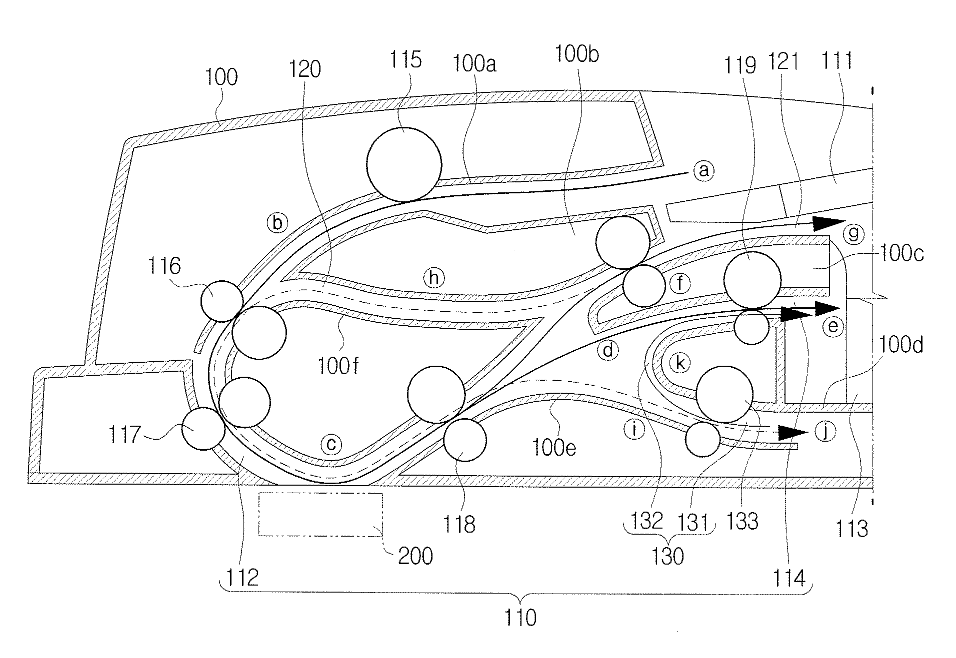
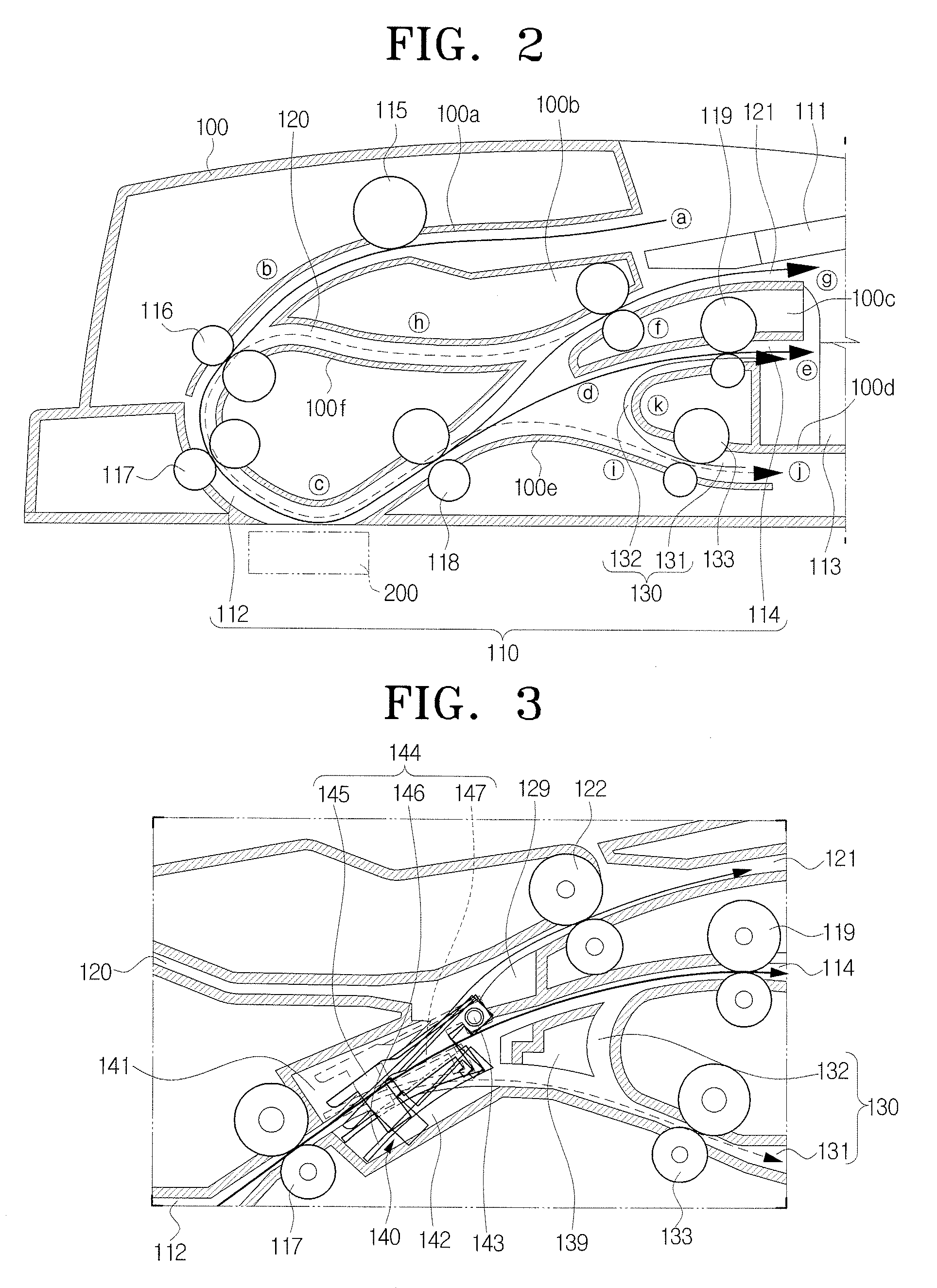
[0037]FIG. 2 is a schematic view exemplifying an automatic document feeder usable in an image forming and / or scanning apparatus according to an embodiment of the present general inventive concept, and FIG. 3 is a detail view exemplifying a portion of the automatic document feeder of FIG. 2. Referring to FIGS. 2 and 3, reference numerals 100 and 200 represent a document feeder frame and a document scanning part, respectively.

[0038]As illustrated in FIGS. 2 and 3, the automatic document feeder includes a single scan path 110, a duplex scan path 120, a document re-reversing path 130, and a document guide unit 140.

[0039]The single s...


PUM


Abstract

An automatic document feeder of an image forming apparatus capable of improving a duplex scanning or printing (copying) efficiency includes a single scan path having a document admission passage to admit a document to a document scanning part and a document discharge passage to discharge the scanned document, a duplex scan path having a first document reversing and waiting passage diverged separately from the document discharge passage on the single scan path at the rear of the document scanning part to reverse the document, one surface of which is scanned, and admit the reversed document again to the document scanning part, and a document re-reversing path having a second document reversing and waiting passage diverged separately from the document discharge passage on the single scan path at the rear of the document scanning part to reverse the document, both surfaces of which are scanned, again and send the re-reversed document to the document discharge passage.

Description

CROSS-REFERENCE TO RELATED APPLICATIONS[0001]This application claims priority under 35 U.S.C. §119(a) of Korean Patent Application No. 10-2006-0088616 filed Sep. 13, 2006, in the Korean Intellectual Property Office, the entire disclosure of which is hereby incorporated by reference.BACKGROUND OF THE INVENTION[0002]1. Field of the Invention[0003]The present general inventive concept relates to an image forming apparatus, such as a multifunction machine or a copier. More particularly, the present general inventive concept relates to an automatic document feeder of an image forming apparatus having a duplex printing function.[0004]2. Description of the Related Art[0005]Generally, an image forming apparatus, such as a multifunction machine, a copier, or the like, is provided with an automatic document feeder, which continuously and automatically feeds a document to be scanned onto a document scanning part of a scanner unit. The automatic document feeder usually has a single scan path, a...

Claims


Application Information

Patent Timeline
Patent Type & Authority Applications(United States)
IPC IPC(8): H04N1/04
CPCG03G15/23G03G2215/00189G03G15/602H04N2201/0091H04N1/0058H04N1/00602H04N1/00615H04N1/00578G03G15/00H04N1/00
Inventor JO, YONG-KON
Owner HEWLETT PACKARD DEV CO LP
Why Eureka
Try Eureka