Heat dissipation device for light emitting diode module

a technology of heat dissipation device and light-emitting diode, which is applied in the direction of lighting and heating apparatus, stationary conduit assemblies, point-like light sources, etc., can solve the problems of degrading the quality of display or illumination, the operation of general led modules has a problem of instability, and the temperature of led modules is rapidly rising

Inactive Publication Date: 2008-03-13
HON HAI PRECISION IND CO LTD
View PDF6 Cites 101 Cited by
  • Summary
  • Abstract
  • Description
  • Claims
  • Application Information

AI Technical Summary

Problems solved by technology

LED modules for use in a display or an illumination device require many LEDs, and most of the LEDs are driven at the same time, which results in a quick rise in temperature of the LED module.
Since generally the LED modules do not have heat dissipation devices with good heat dissipating efficiencies, operation of the general LED modules has a problem of instability because of the rapid build up of heat.
Consequently, the light from the LED module often flickers, which degrades the quality of the display or illumination.

Method used


Image

  • Heat dissipation device for light emitting diode module
  • Heat dissipation device for light emitting diode module
  • Heat dissipation device for light emitting diode module

Examples


Embodiment Construction

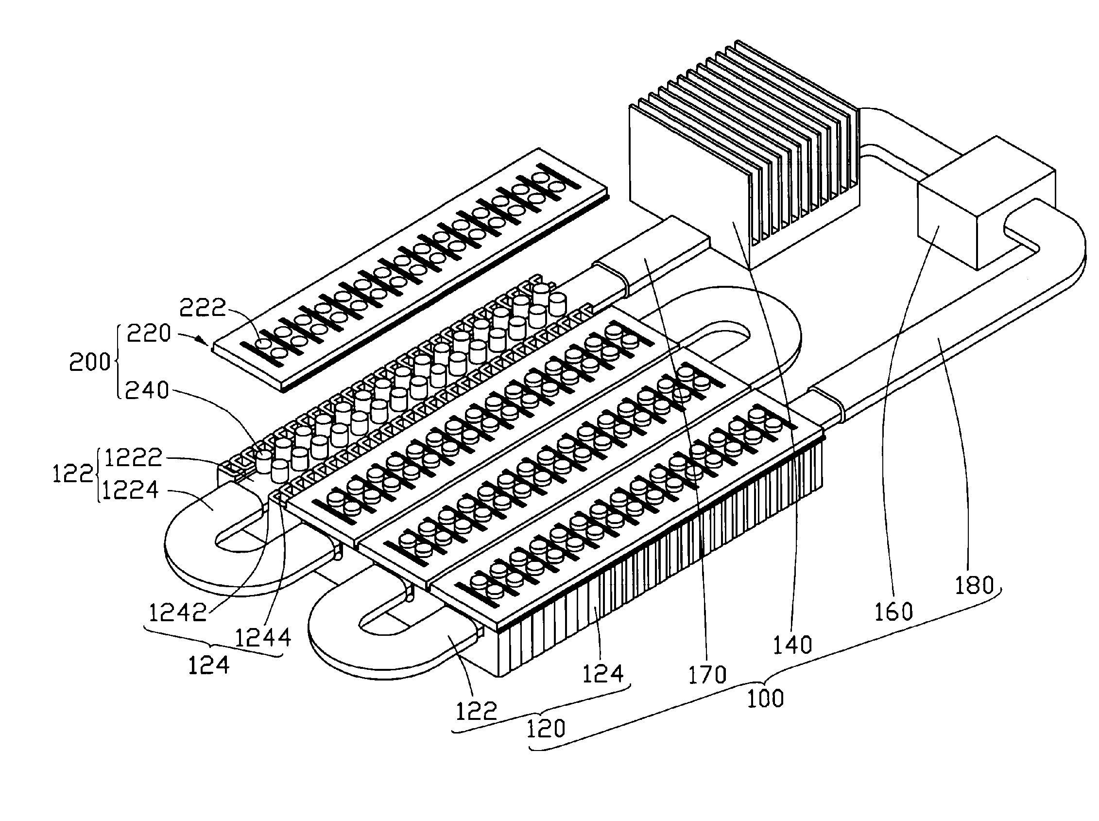
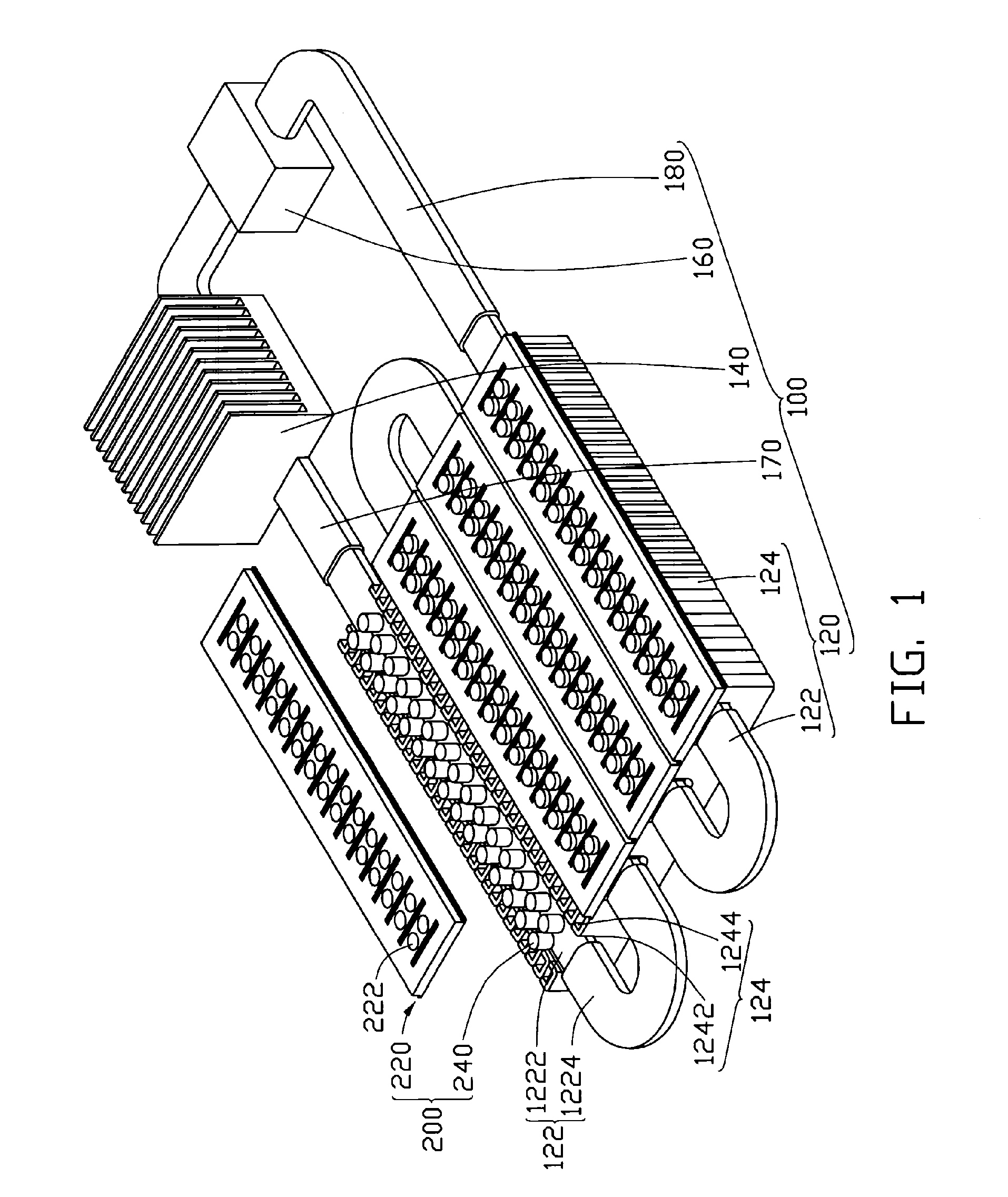
[0014]Referring to FIG. 1, a heat dissipation device 100 in accordance with a first preferred embodiment is illustrated. The heat dissipation device 100 is used to cool down an LED module 200 to keep the LED module 200 working within an acceptable temperature range.

[0015]In this embodiment, the LED module 200 comprises several juxtaposed printed circuit boards 220 and a plurality of LEDs 240 electrically bonded to the printed circuit boards 220. Each printed circuit board 220 has a plurality of through holes 222 defined therein. The through holes 222 are arrayed in rows and lines for the LEDs 240 extending therethrough. Alternatively, these printed circuit boards 220 can be replaced by a larger single printed circuit board, which has a matrix of through holes defined therein. The LEDs 240 are installed into the corresponding through holes 222 of the printed circuit boards 220, and electrically connected to circuits (not shown) provide on the printed circuit boards 220. Therefore, th...


PUM


Abstract

A heat dissipation device for a light emitting diode (LED) module includes a liquid cooling system. The liquid cooling system includes a heat-absorbing member, which includes an inlet, an outlet and at least one pipe extending between the inlet and the outlet. The inlet and the outlet are provided for permitting liquid to flow through the at least one pipe, which is in thermal contact with at least one LED of the LED module.

Description

FIELD OF THE INVENTION[0001]The present invention relates to a heat dissipation device, more particularly to a heat dissipation device for a light emitting device module.DESCRIPTION OF RELATED ART[0002]A light emitting diode (LED) is a device for transferring electricity to light by using a theory that, if a current is made to flow in a forward direction in a junction comprising two different semiconductors, electrons and holes are coupled at a junction region to generate a light beam. The LED has an advantage in that it is resistant to shock, and has an almost eternal lifetime under a specific condition, so more and more LED modules with different capabilities are being developed.[0003]LED modules for use in a display or an illumination device require many LEDs, and most of the LEDs are driven at the same time, which results in a quick rise in temperature of the LED module. Since generally the LED modules do not have heat dissipation devices with good heat dissipating efficiencies,...

Claims


Application Information

Patent Timeline
Patent Type & Authority Applications(United States)
IPC IPC(8): F21V29/00
CPCF21V29/30F21Y2101/02F28D2021/0029F28D1/05366F28D15/00F28D1/0478F21V29/56F21V29/70F21Y2115/10
Inventor LAI, CHENG-TIENZHOU, ZHI-YONGDING, QIAO-LI
Owner HON HAI PRECISION IND CO LTD
Why Eureka
Try Eureka