Liquid-cooled LED lighting device

a led lighting and liquid-cooled technology, applied in the direction of lighting support devices, semiconductor/solid-state device details, lighting and heating apparatus, etc., can solve the problems of high cooling effect, limit to the increase in output power, and may not be able to achieve a higher current supply of leds. , to achieve the effect of high cooling

Active Publication Date: 2010-10-21
STANLEY ELECTRIC CO LTD
View PDF7 Cites 46 Cited by
  • Summary
  • Abstract
  • Description
  • Claims
  • Application Information

AI Technical Summary

Benefits of technology

[0008]However, with the above natural cooling-heat dissipating structures, like the lighting device disclosed in Japanese Patent App

Problems solved by technology

However, with the above natural cooling-heat dissipating structures, like the lighting device disclosed in Japanese Patent Application Laid-Open No. 2002-299700, a high cooling effect is not expected, and there is a limit to the increase in the output power.
Accordingly, when the lighting device not in the water it is mainly cooled by natural heat dissipation only, so that a higher current supply to the LED may not be possible.
In a conventional lighting device, however, such a housing is mainly cooled by natural heat dissipation only, and accordingly, any structure and/or mechanism for forced cooling of a housing is not adopted.
If such a liquid cooling system is broken, even when a separate air-cooling system is provided, the overheating of the LED may not be completely prevented.
When a lighting device is used in areas such as gas stations, chemical plants, and the li

Method used


Image

  • Liquid-cooled LED lighting device
  • Liquid-cooled LED lighting device
  • Liquid-cooled LED lighting device

Examples


Embodiment Construction

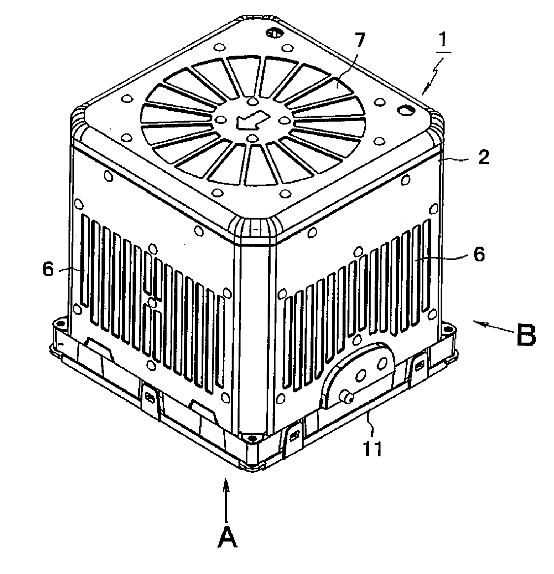
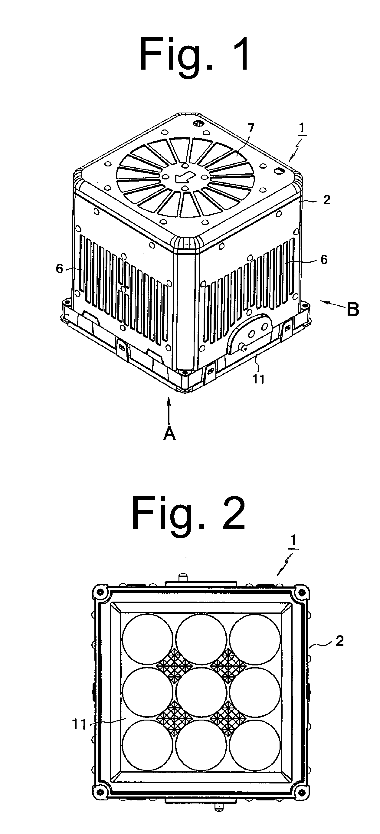
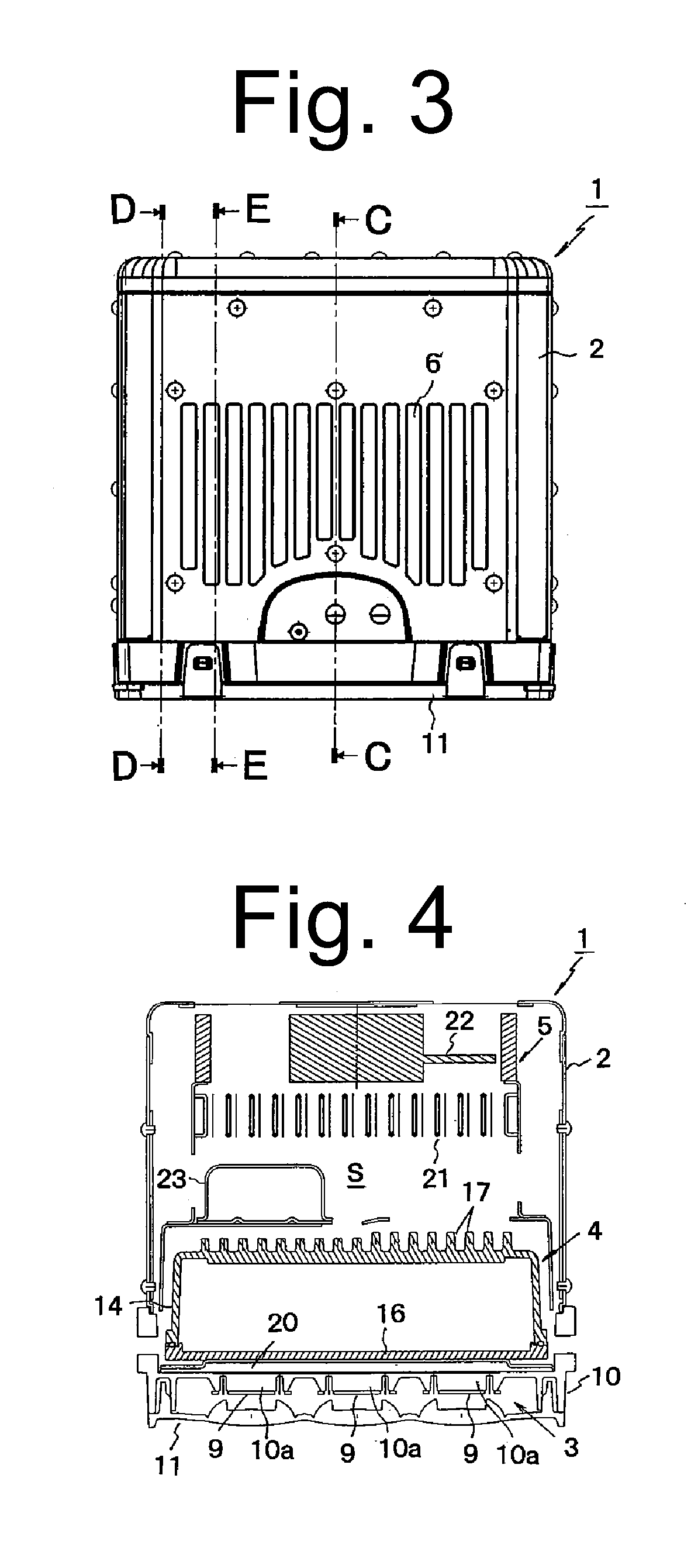
[0083]A description will now be made below to exemplary embodiments of liquid-cooled LED lighting devices of the presently disclosed subject matter with reference to the accompanying drawings.

[0084]FIG. 1 is a perspective view illustrating a liquid-cooled LED lighting device according to an exemplary embodiment of the presently disclosed subject matter. FIG. 2 is a diagram illustrating the liquid-cooled LED lighting device viewed from arrow A in FIG. 1. FIG. 3 is a diagram illustrating the liquid-cooled LED lighting device viewed from arrow B in FIG. 1. FIG. 4 is a cross-sectional view taken along line C-C of FIG. 3. FIG. 5 is a cross-sectional view taken along line D-D of FIG. 3. FIG. 6 is a cross-sectional view taken along line E-E of FIG. 3. FIG. 7 is an exploded perspective view of the liquid-cooled LED lighting device of FIG. 1. FIG. 8 is a diagram illustrating an example of a basic configuration of a liquid cooling system for the liquid-cooled LED lighting device of FIG. 1.

[00...


PUM


Abstract

A cooling liquid can be circulated in a liquid cooling system, so that a light source unit and a control unit can be forcedly cooled by the cooling liquid. Thus, a temperature increase in these components can be suppressed, thereby achieving an increase in the output power of a liquid-cooled LED lighting device. The liquid-cooled LED lighting device can include a housing, a light source unit having LEDs as light sources, a liquid cooling system, and a control unit to control the light source unit to be turned on. The liquid cooling system can include a heat receiving jacket, a radiator, a circulation pump and a fan. The light source unit and the control unit can be disposed with the heat receiving jacket of the liquid cooling system interposed therebetween. Further, one surface of the control unit can be brought in close contact with the heat receiving jacket while a heat radiation portion (e.g., fins or pins) can be provided at an other surface of the control unit.

Description

[0001]This application claims the priority benefit under 35 U.S.C. §119 of Japanese Patent Applications No. 2009-099141 filed on Apr. 15, 2009, No. 2009-099171 filed on Apr. 15, 2009, No. 2009-099683 filed on Apr. 16, 2009, and No. 2009-124954 filed on May 25, 2009, which are hereby incorporated in their entirety by reference.TECHNICAL FIELD[0002]The presently disclosed subject matter relates to a liquid-cooled LED lighting device that employs a forced cooling system for cooling both a light source unit and a control unit by a coolant. The presently disclosed subject matter also relates to a liquid-cooled LED lighting device that forcedly cools a light source unit by means of liquid as well as forcedly cools a housing accommodating the light source unit by flowing air. The presently disclosed subject matter also relates to a hybrid type liquid-cooled LED lighting device including a liquid cooling system for cooling a light source unit and an air cooling unit.BACKGROUND ART[0003]In r...

Claims


Application Information

Patent Timeline
IPC IPC(8): H01J61/52F21V29/00
CPCF21K9/00F21V29/83F21V29/02F21V29/30F21Y2101/02H01L23/473F21V29/402H01L2924/0002F21S48/325F21V29/80F21V29/58F21V29/673F21V29/75H01L2924/00F21V29/56F21V29/677F21Y2115/10F21S45/43F21S45/46F21V29/00
Inventor YATSUDA, YASUSHIHIRAMOTO, YASUSHIKOIKE, TERUO
Owner STANLEY ELECTRIC CO LTD
Why Eureka
Try Eureka