Thermal interposer liquid cooling system

a technology of liquid cooling system and thermocouple, which is applied in the direction of indirect heat exchanger, electrical apparatus construction details, lighting and heating apparatus, etc., can solve the problems of individual integrated circuits, heat generation of individual components, and power consumption of motherboards and various auxiliary components,

Active Publication Date: 2012-09-25
ASETEK DANMARK
View PDF13 Cites 51 Cited by
  • Summary
  • Abstract
  • Description
  • Claims
  • Application Information

AI Technical Summary

Problems solved by technology

During operation, the motherboard and various auxiliary components consume power and generate heat.
Individual integrated circuits, such as, for example, central processing units (CPUs), graphics processing units (GPUs), memory modules, etc. may generate significant amounts of heat during operation.
This heat may result in undesirably high temperature at the components or localized hot spots within the chassis.
Failure to maintain adequate temperature control within the chassis, and at individual integrated circuits, can degrade system performance and may eventually lead to component failure.
However, as personal computer systems include increasing numbers of individual components, such as, for example, integrated circuits and graphics display adapters, a supply cooling fan may be inadequate to maintain the necessary operating temperatures within the chassis environment.
However, these specialized liquid cooling systems are not adapted for use with a wide variety of components or adapter boards in a personal computer system.
Furthermore, once such liquid cooling systems are installed, often it is difficult to replace, insert, or remove components requiring cooling from the system.
These systems often add significant space requirements to the adapter card, necessitating the use of two adapter “slots” or bays.
Additionally, by continuing to utilize thermal radiators for air cooling, these systems contribute heat to the internal environment within the computer chassis, increasing the strain on other cooling components.

Method used


Image

  • Thermal interposer liquid cooling system
  • Thermal interposer liquid cooling system
  • Thermal interposer liquid cooling system

Examples


Embodiment Construction

[0018]The following detailed description illustrates the invention by way of example and not by way of limitation. The description enables one skilled in the art to make and use the present disclosure, and describes several embodiments, adaptations, variations, alternatives, and uses of the present disclosure, including what is presently believed to be the best mode of carrying out the present disclosure.

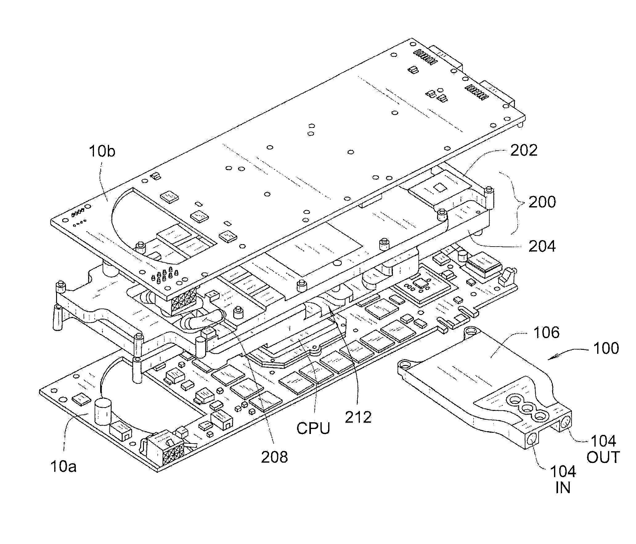
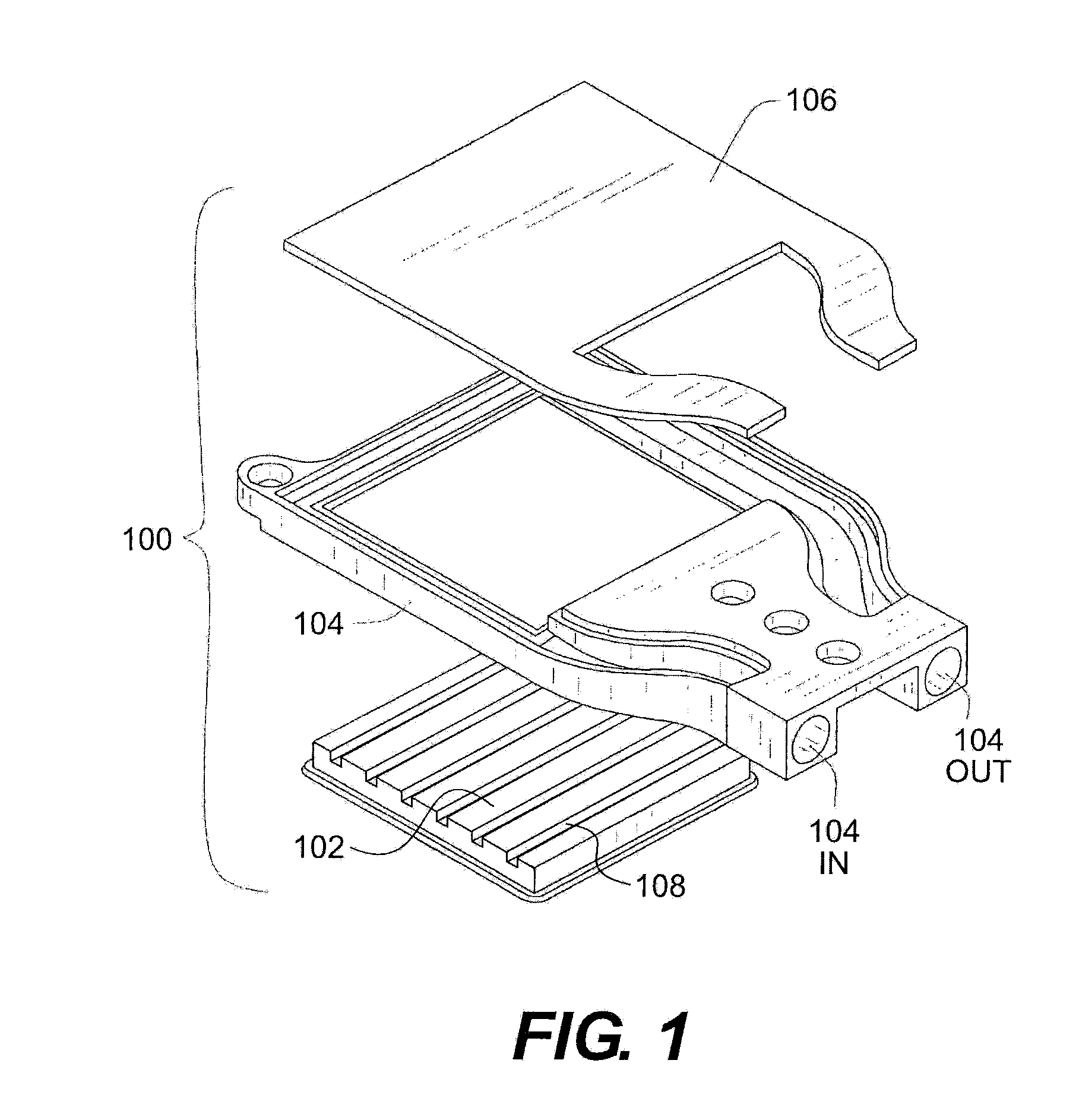
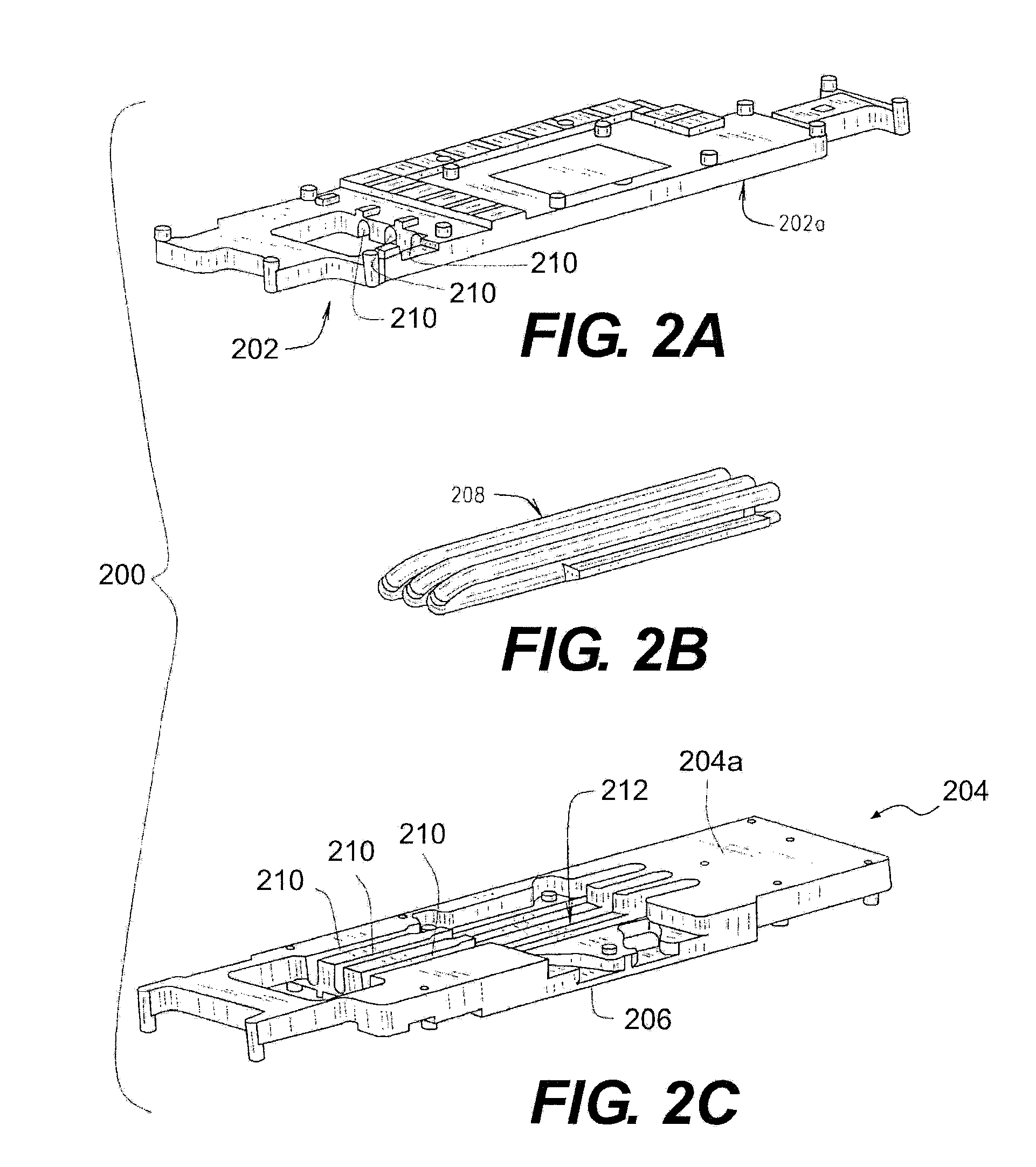
[0019]Personal computers, network servers, and many other variations of computing devices employ electronic sub-components such as circuit boards, adapter cards, daughter cards, DC / DC converters, hard drives, and optical drives mounted in an enclosed case or chassis. These various electronic sub-components, including a common power supply, generate heat during operation which must be dissipated from the chassis or case to avoid heat-induced damage or overheating of the various components. Common methods for extracting heat from the internal volume of a computer case or chassis inclu...


PUM


Abstract

A thermal interposer for a heat-generating electronic component includes a thermally conducting body that is configured to be thermally coupled to the electronic component. The thermally conducting body may include a first region that is located on a first face of the thermally conducting body. The first region may be adapted to be in thermal contact with a surface of the electronic component. The thermally conducting body may also include a second region located on a second face that is opposite the first face of the thermally conducting body. The thermal interposer may also include a cold plate assembly that is removably coupled to the thermally conducting body. The cold plate assembly may be in thermal contact with the second region of the thermally conducting body. The cold plate assembly may include an inlet adapted to receive a cooling liquid into the cold plate assembly and an outlet adapted to discharge the cooling liquid from the cold plate assembly.

Description

CROSS-REFERENCE TO RELATED APPLICATIONS[0001]This application is a Continuation-in-Part application of PCT International Application No. PCT / US09 / 044,813 filed on May 21, 2009, which claims the priority of U.S. Provisional Patent Application Ser. No. 61 / 054,992 filed on May 21, 2008, both of which are incorporated herein by reference in their entirety.TECHNICAL FIELD[0002]The present invention is related generally to a system for cooling electronic components, and heat sources associated with electronic components.BACKGROUND[0003]Computer systems, such as, for example, personal computers, which are designed for desktop or under-desk use are typically characterized by a main-board or motherboard housed in a chassis or case. Auxiliary components additionally contained within the chassis or case may include, among others, network adapter circuit boards, modems, specialized adapters, and graphics display adapters. These auxiliary components may receive power through connection to the mo...

Claims


Application Information

Patent Timeline
Patent Type & Authority Patents(United States)
IPC IPC(8): H05K7/20
CPCF28D15/00F28D15/02G06F1/20H01L23/473H05K7/20254F28D2021/0019G06F2200/201H01L23/427H01L2924/0002H01L2924/00
Inventor ALYASER, MONEM H.RICE, JEREMY A.
Owner ASETEK DANMARK
Why Eureka
Try Eureka