Sparsely Spaced Array Led Headlamp

a technology of led headlamps and arrays, applied in the field of automotive headlamps, can solve the problems of conventional headlamp system optics and designs not being appropriate for led headlamps, optical waste of emitted light,

Inactive Publication Date: 2008-03-13
MAGNA INTERNATIONAL INC
View PDF10 Cites 23 Cited by
  • Summary
  • Abstract
  • Description
  • Claims
  • Application Information

AI Technical Summary

Benefits of technology

[0007] Preferably, the first array of illumination light sources comprises a plurality of fiber optic cables, one end of each respective fiber optic cable being optically coupled to a respective one of a plurality of LED light sources, the other end of each respective fiber optic cable being substantially arranged corresponding to the illumination beam pattern, whereby the light emitted by the LED light sources is transferred by the fiber optic cables to the first lens in substantially the illumination beam pattern. Also preferably, different ones of the light sources in the light source array can be illuminated to form different illumination beam patterns and these patterns can include high beam, low beam, fog lamp and day time running light patterns.

Problems solved by technology

However, even with these recent advances, individual LEDs emit much less light than the incandescent or gas discharge light sources they are replacing and thus multiple LED devices must be employed within the headlamp to obtain the necessary illumination levels.
Conventional headlamp system optics employ reflectors, masks and / or lenses to direct and focus the light emitted by very few, typically one or two, light sources and these optics can waste emitted light as the light emitted by such sources is abundant.
As LED-based headlamps will have many light sources and as the emitted illumination must be carefully managed, as the level of the emitted illumination is low compared to incandescent or gas discharge sources, conventional headlamp system optics are not appropriate for LED-based headlamps.
Accordingly, conventional headlamp system optics and designs are not appropriate to LED headlamps.

Method used


Image

  • Sparsely Spaced Array Led Headlamp
  • Sparsely Spaced Array Led Headlamp
  • Sparsely Spaced Array Led Headlamp

Examples


Embodiment Construction

[0015] In prior at approaches to designing LED-based headlamps, designers have tried to employ LED sources in manners which emulated a point source, such as an incandescent bulb or gas discharge bulb. The present inventor has determined that advantages can be obtained when constructing LED-based headlamps by arranging the LED light sources such that they are employed as a relatively sparse arrangement which generally corresponds to the desired beam pattern to be formed by the headlamp.

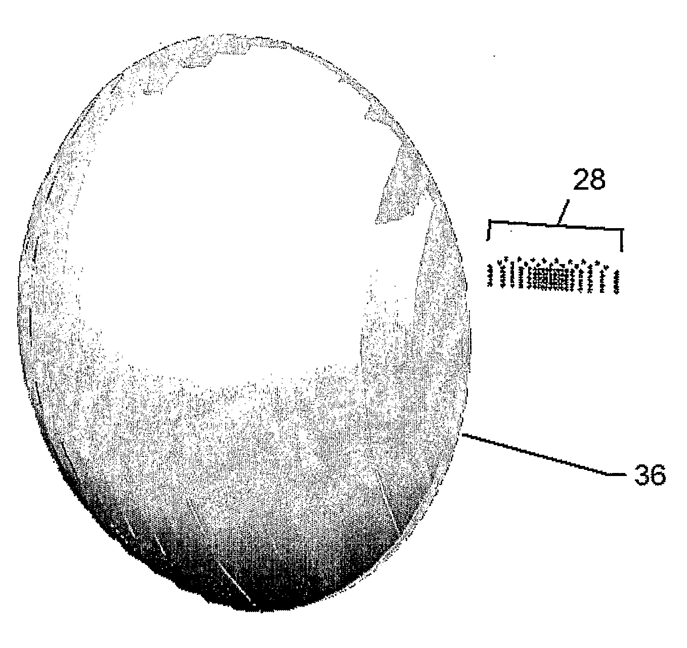
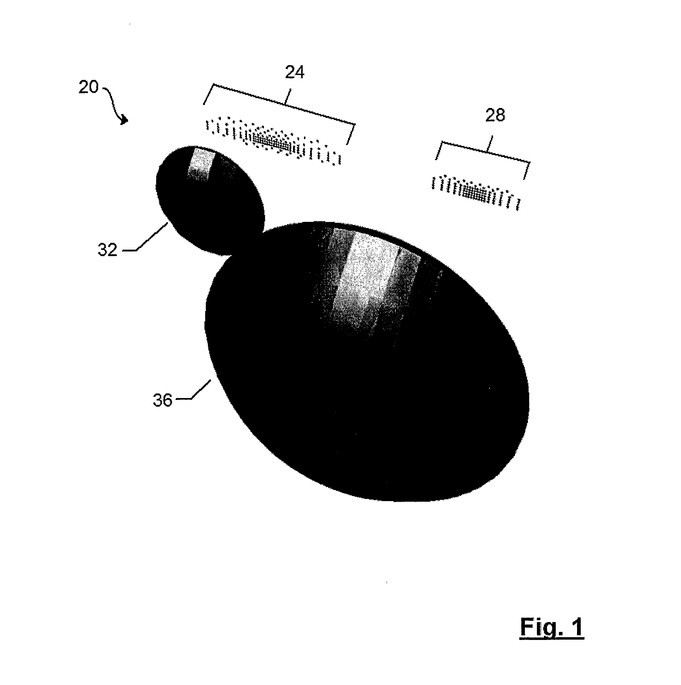
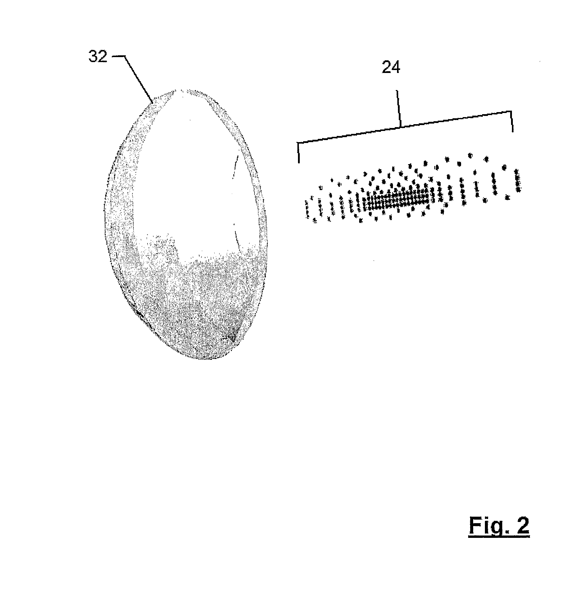
[0016] A headlamp in accordance with the present invention is indicated generally at 20 in FIG. 1. As illustrated, headlamp 20 includes two light source arrays 24 and 28 and two lenses 32 and 36. Each light source array 24, 28 is paired with a respective lens 32, 36 to obtain an illumination beam pattern former and the illumination beam pattern former comprising light source array 24 and lens 32 is shown in more detail in FIG. 2. This illumination beam pattern former is referred to herein as the sprea...


PUM


Abstract

A headlamp comprising at least one array of illumination light sources, the light sources positioned substantially corresponding to a desired illumination beam pattern for the headlight, the light from the light source of the array being provided to a lens which projects the light in the illumination beam pattern. Preferably, the light is provided from LED light sources which are coupled to fiber optic cables to form the array of illumination source. Also preferably, the light sources can be illuminated in different patterns, to provide different illumination beam patterns.

Description

FIELD OF THE INVENTION [0001] The present invention relates to automotive headlamps. More specifically, the present invention relates to LED-based headlamps. BACKGROUND OF THE INVENTION [0002] With recent advance is semiconductor technology, the output power of white LEDs has increased to the point where automotive headlamps employing such LEDs as light sources are being developed. However, even with these recent advances, individual LEDs emit much less light than the incandescent or gas discharge light sources they are replacing and thus multiple LED devices must be employed within the headlamp to obtain the necessary illumination levels. At the same time, for cost and other reasons, it is desired to employ as few LED light sources as necessary to meet illumination levels in the headlamp. [0003] Conventional headlamp system optics employ reflectors, masks and / or lenses to direct and focus the light emitted by very few, typically one or two, light sources and these optics can waste ...

Claims


Application Information

Patent Timeline
Patent Type & Authority Applications(United States)
IPC IPC(8): F21S8/10G02B6/04
CPCF21S48/1154F21S48/1233F21Y2101/02F21S48/1747F21S48/1241F21Y2105/12F21Y2115/10F21S41/28F21S41/24F21S41/663F21S41/153
Inventor WOODWARD, RONALD O.
Owner MAGNA INTERNATIONAL INC
Why Eureka
Try Eureka