Process cartridge and image forming apparatus

a technology of image forming apparatus and process cartridge, which is applied in the direction of optics, electrographic processes, instruments, etc., can solve the problems of generating heat, difficult to remove heat caused, and easy toner melt due to self-heating,

Inactive Publication Date: 2008-03-13
RICOH KK
View PDF9 Cites 56 Cited by
  • Summary
  • Abstract
  • Description
  • Claims
  • Application Information

AI Technical Summary

Benefits of technology

[0011]It is an object of the present invention to at least

Problems solved by technology

Accordingly, these make it difficult to remove heat caused by self-heating of the process cartridge, due to a small number of spaces.
Further, the toner apt to melt due to the self-heating is susceptible to damage.
Because the drive transmission is generally gathered to one sid

Method used


Image

  • Process cartridge and image forming apparatus
  • Process cartridge and image forming apparatus
  • Process cartridge and image forming apparatus

Examples


Embodiment Construction

[0046]Exemplary embodiments of the present invention are explained in detail below referring to the accompanying drawings.

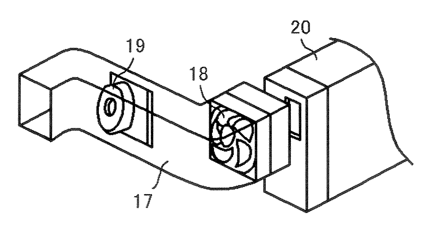
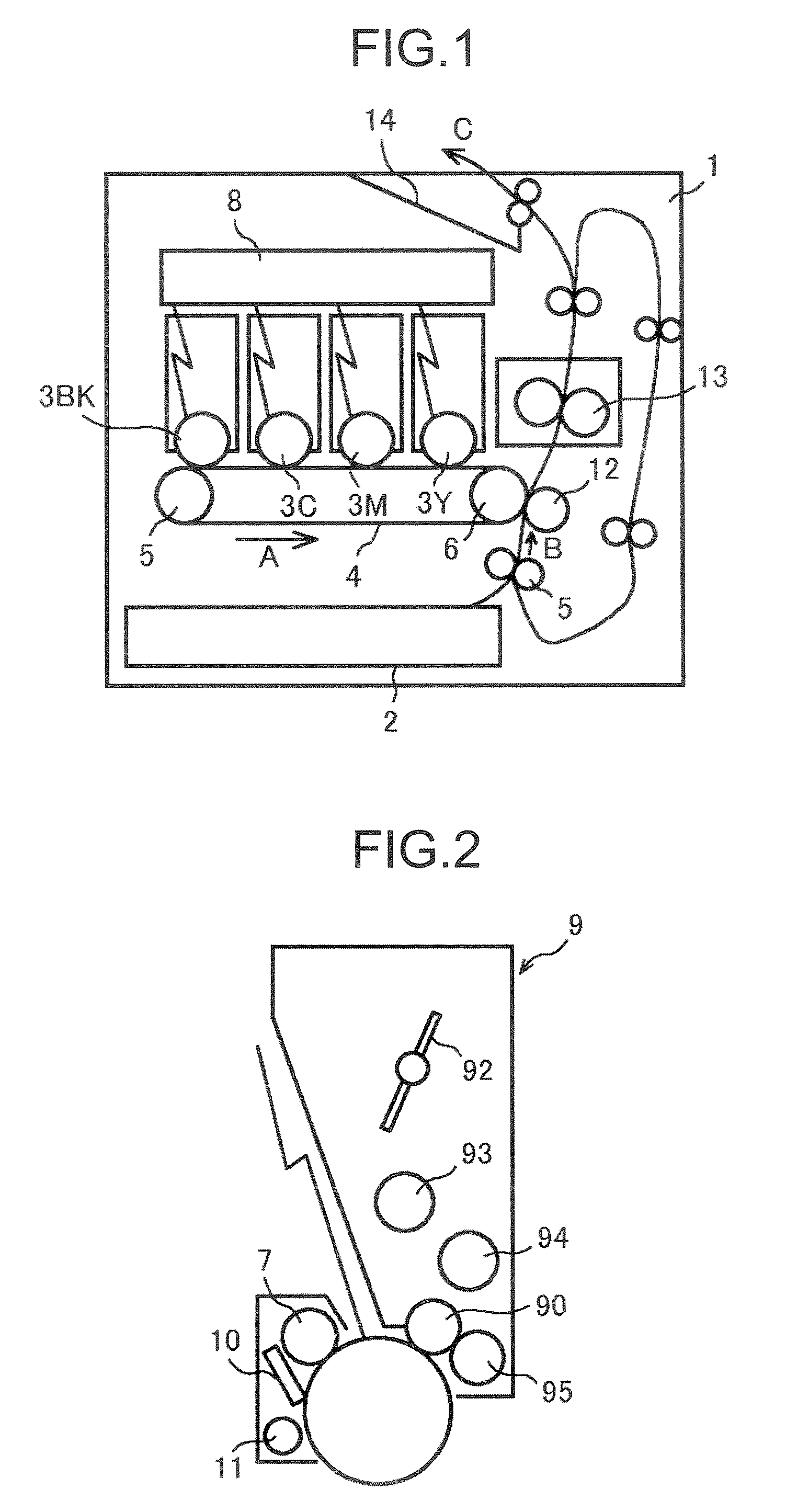
[0047]FIG. 1 is a schematic diagram of a color printer as an example of an image forming apparatus according to an embodiment of the present invention. The image forming apparatus includes a body 1 that accommodates therein four photoconductors 3Y, 3M, 3C, and 3BK for yellow, magenta, cyan, and black. These photoconductors 3Y, 3M, 3C, and 3BK are hereinafter collectively designated by the reference numeral 3 unless they are required to be differentiated. Although the photoconductors 3 as described herein are in a drum shape, they can be an endless belt. An intermediate transfer medium 4, which is an example of a transfer material, is arranged opposed to the photoconductors 3Y through 3BK. The intermediate transfer medium 4 shown here includes an endless belt wound around a plurality of supporting rollers 5 and 6, and movably driven in an arrow A direction. A colo...


PUM


Abstract

A process cartridge includes a photoconductor driven by gears, a developing roller, an agitator. The process cartridge is mounted on an image forming apparatus that forms an image with toner. The process cartridge includes an air inlet and an air outlet on a side plate thereof. The gears are arranged along a path between the air inlet and the air outlet.

Description

CROSS-REFERENCE TO RELATED APPLICATIONS[0001]The present application claims priority to and incorporates by reference the entire contents of Japanese priority documents, 2006-246681 filed in Japan on Sep. 12, 2006 and 2006-342912 filed in Japan on Dec. 20, 2006.BACKGROUND OF THE INVENTION[0002]1. Field of the Invention[0003]The present invention relates to a process cartridge and an image forming apparatus.[0004]2. Description of the Related Art[0005]In recent years, colorization has been extensively applied to image forming apparatuses such as copiers, printers, facsimile machines, and multifunction products (MFPs) with a plurality of functions. Particularly, a tandem type that has a plurality of image bearing members excels in speed and is becoming a mainstream. In the tandem type image forming apparatus, an apparatus used by arranging four process cartridges in parallel is known. Because miniaturization of the apparatus is an element that directly leads to customers' convenience,...

Claims


Application Information

Patent Timeline
IPC IPC(8): G03G21/20
CPCG03G21/1857G03G21/206G03G2221/183
Inventor IDEHARA, RYOHKITA, NOBUHIKOONUMA, SEIKONDO, KAZUYOSHIFURUICHI, YUUSUKEOKANO, TADASHIHAGIWARA, GENTATADA, KAORU
Owner RICOH KK
Why Eureka
Try Eureka