Cooling system of an internal combustion engine having charge air feed

a technology of charge air feed and cooling system, which is applied in the direction of machines/engines, mechanical equipment, non-fuel substance addition to fuel, etc., can solve the problems of lower engine performance and achieve the effect of simple control technology design

Active Publication Date: 2008-03-20
MAN NUTZFAHRZEUGE AG
View PDF12 Cites 52 Cited by
  • Summary
  • Abstract
  • Description
  • Claims
  • Application Information

AI Technical Summary

Benefits of technology

This patent describes a new cooling system for supercharged internal combustion engines that prevents damage from overheating during certain stages of operation. It allows for faster heating up of the engine at high temperatures while still ensuring reliable protection against excessive coolant flow. The system has been designed with simplicity and flexibility in mind, allowing it to quickly adapt to changing conditions and providing efficient cooling even under extreme circumstances.

Problems solved by technology

Modern internal combustion engines require intercooling to cool the air before it reaches the engine. While traditional methods involve cooling both the hot parts (turbocharger) and the cold part (charge air compressor), these new techniques only focus on the cold part - reducing energy waste and improving efficiency. However, current cooling systems operate constantly, regardless of whether they're necessary, leading to unnecessary wear and tear on certain components. Therefore, the problem addressed in this patent is how to improve cooling efficiencies without affecting component longevity.

Method used


Image

  • Cooling system of an internal combustion engine having charge air feed
  • Cooling system of an internal combustion engine having charge air feed
  • Cooling system of an internal combustion engine having charge air feed

Examples


Embodiment Construction

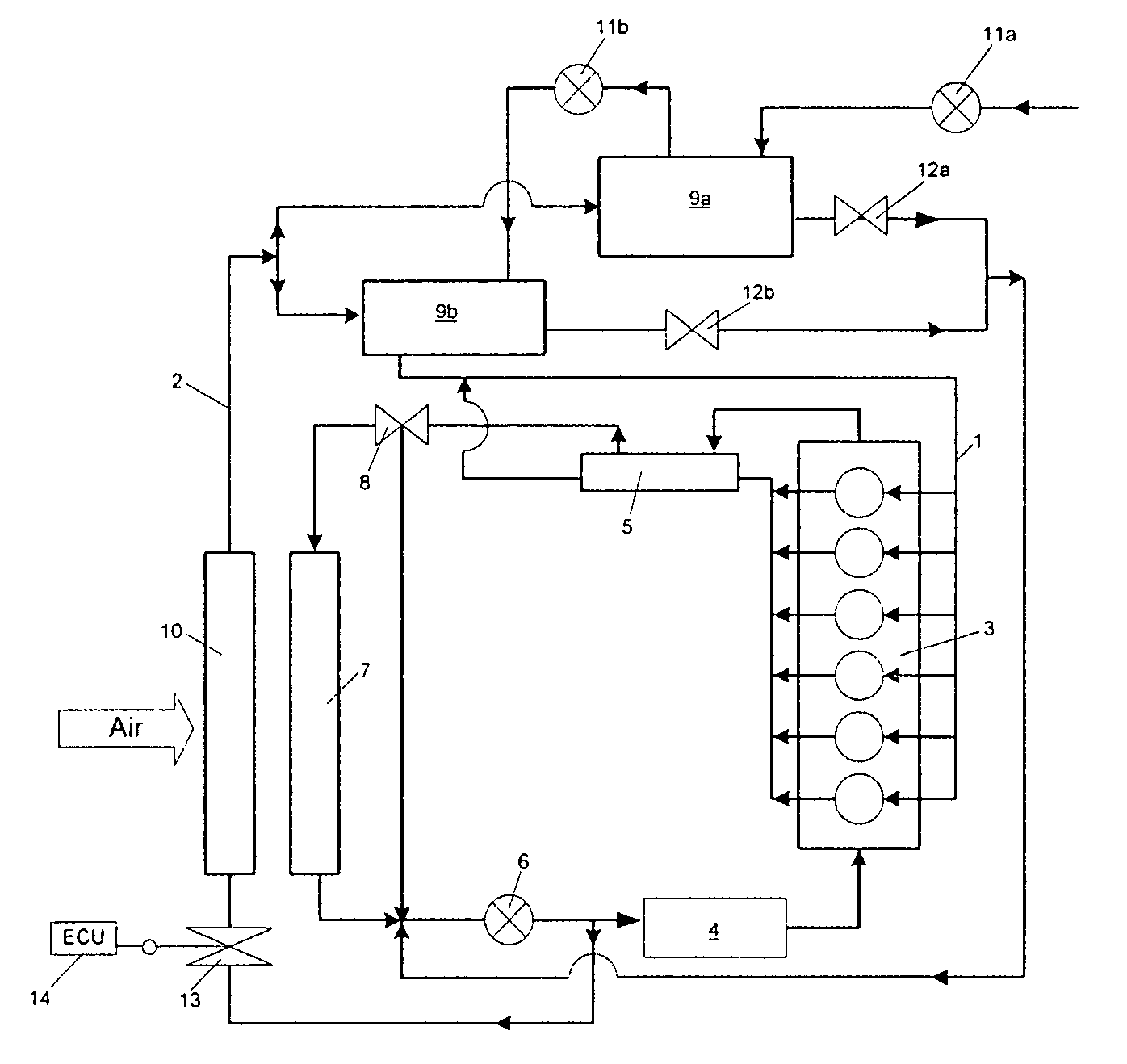
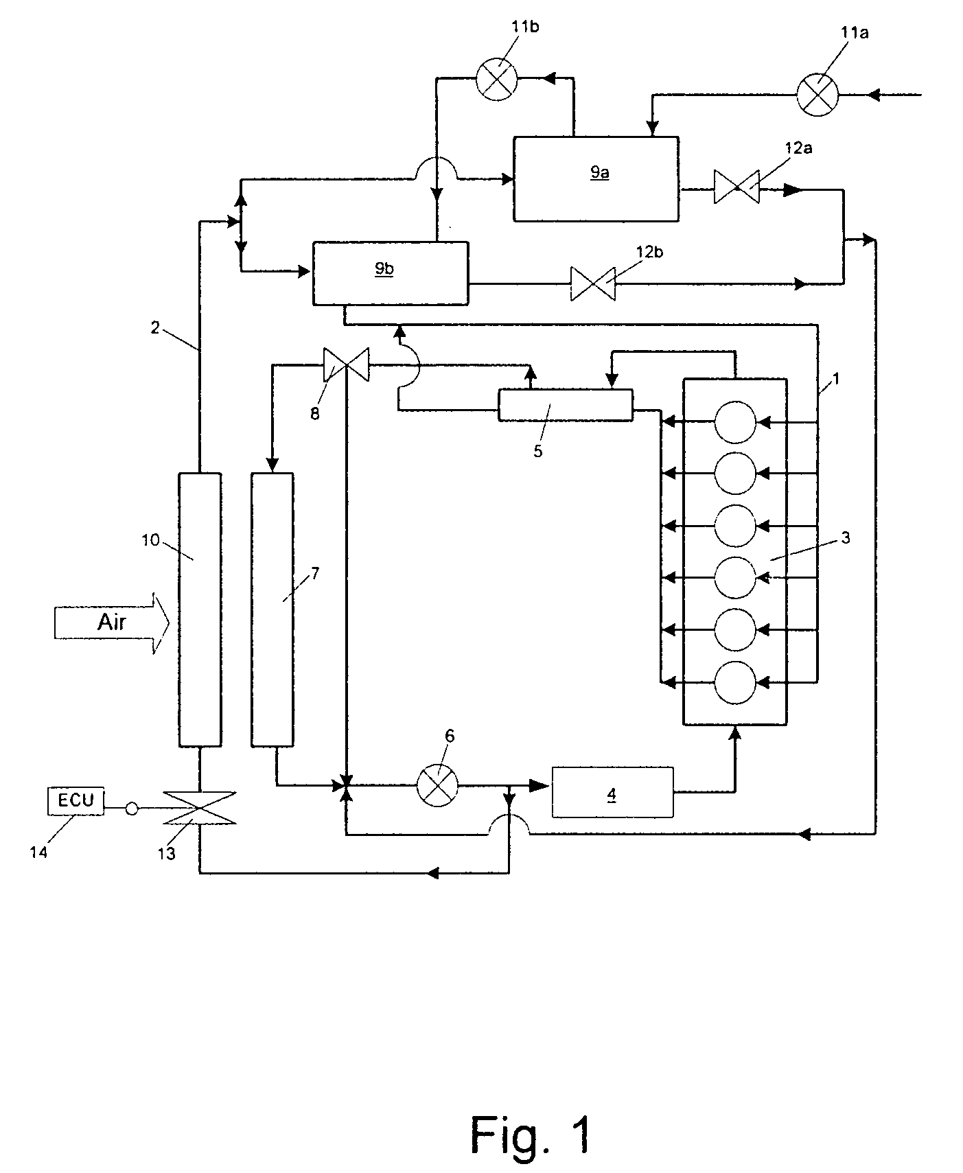
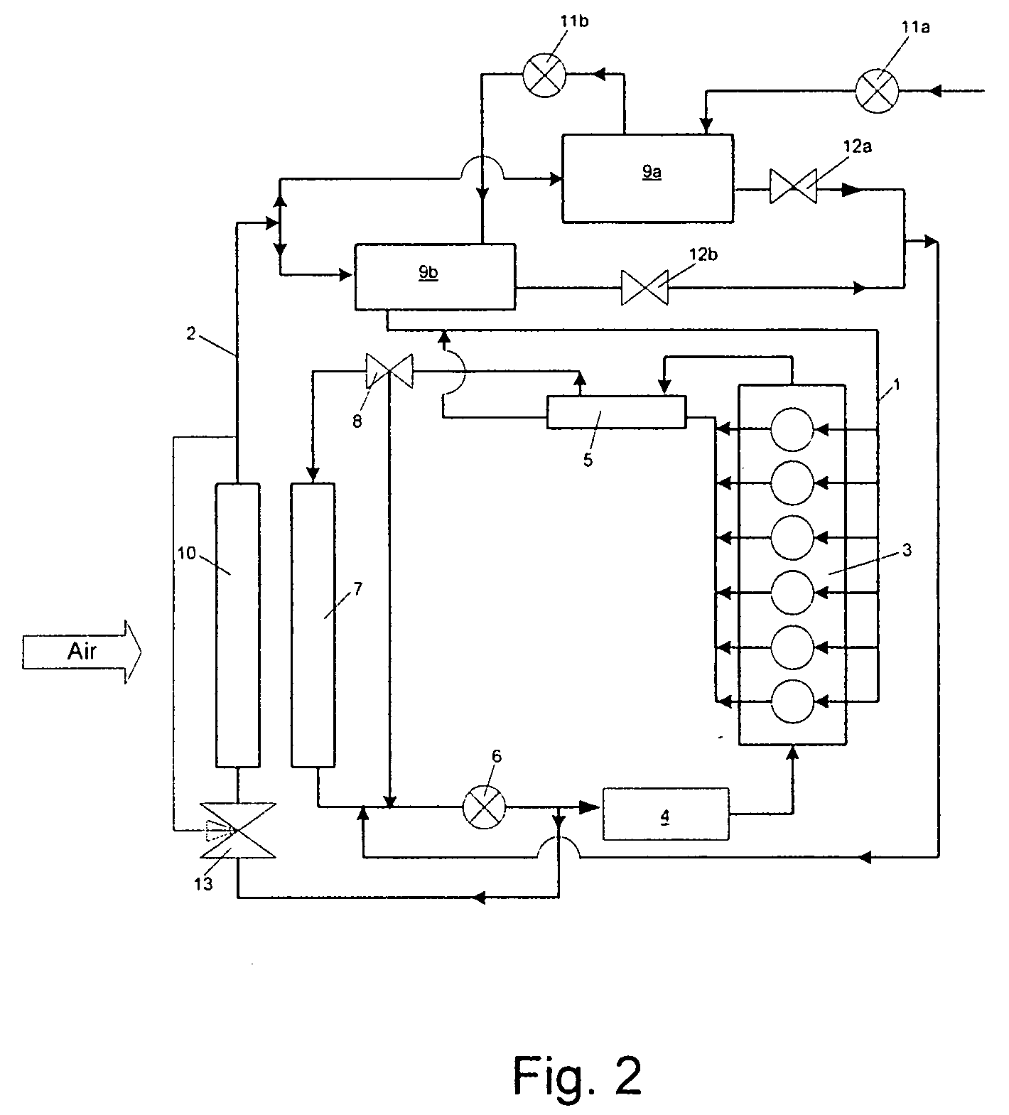
[0022]FIG. 1 shows a cooling system according to the present invention having a first cooling loop 1 designed as a high-temperature cooling loop and a second cooling loop 2 designed as a low-temperature cooling loop. In the exemplary embodiment shown of a motor vehicle cooling system, for example, as is used in modern utility vehicles, in particular in trucks and buses, an internal combustion engine 3, an oil heat exchanger 4, an exhaust gas heat exchanger 5, a coolant pump 6, and an air-cooled high-temperature heat exchanger 7 are hydraulically and thermally incorporated in the high-temperature cooling loop 1. Heat is dissipated from the above-mentioned vehicle components and transferred via the high-temperature heat exchanger 7 to the ambient air via the coolant conveyed in the first cooling loop 1, i.e., the high-temperature cooling loop.

[0023]A thermostat 8 is provided inside the first cooling loop 1, which thermostat regulates the coolant throughput through the high-temperature...


PUM


Abstract

A method and a system for cooling an internal combustion engine (3) having charge air feed, which has a first (1) and a second (2) cooling loop, of which the first cooling loop (1) is operated at a higher temperature level than the second cooling loop (2), and in which the charge air feed has at least one intercooling unit (9) which is thermally coupled to the second cooling loop (2), having a controllable coolant throughput. The system includes at least one shutdown element (13) in the second cooling loop (2) for throttling the coolant throughput in the second cooling loop (2) to 0 (zero), i.e., the coolant throughput may be shut down during the operation of the internal combustion engine (3) as a function of an operating parameter of a vehicle component.

Description


Claims


Application Information

Patent Timeline
Owner MAN NUTZFAHRZEUGE AG
Why Eureka
Try Eureka