Impact damper mechanism

a damper mechanism and gear technology, applied in the direction of friction gearings, belts/chains/gears, gear teeth, etc., can solve the problems of reducing the size and cost of the assembly, affecting and the failure of the gear teeth, so as to reduce the destructive force of the gear and reduce the effect of damping the rotational velocity and angular acceleration of the gear

Inactive Publication Date: 2008-03-20
DELPHI TECH INC
View PDF2 Cites 6 Cited by
  • Summary
  • Abstract
  • Description
  • Claims
  • Application Information

AI Technical Summary

Benefits of technology

[0004]The present invention provides a method and apparatus for reducing destructive forces on a gear caused by abrupt stopping of the gear by reducing or damping the rotational velocity and angular acceleration of a gear as the gear reaches its stopping point.

Problems solved by technology

In their typical operating environment, these components are subject to frequent and abrupt stopping movements when reaching their stopping points which subject the gears and surrounding components to high stresses that can result in a breakdown of the gear teeth and failure of the part.
While various attempts have been made to dampen the abrupt stopping movement of the gear, these attempts usually involve the addition of separately mounted components which undesirably add to the size and cost of the assembly.

Method used


Image

  • Impact damper mechanism
  • Impact damper mechanism
  • Impact damper mechanism

Examples


Embodiment Construction

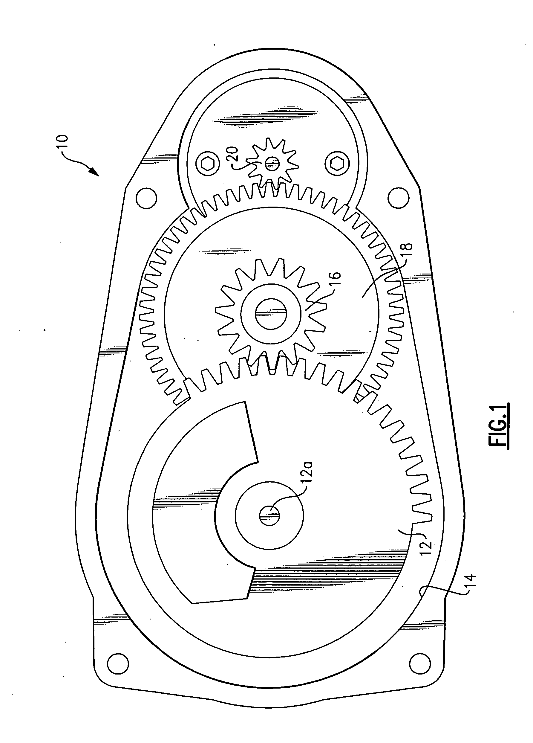
[0015]Referring now to the drawings, there is seen in FIG. 1 one embodiment of the invention incorporated into an electronic throttle control (ETC) 10. It is understood, however, that the invention is applicable to any type of apparatus having one or more gears where dampening of the gear stopping movement is desired.

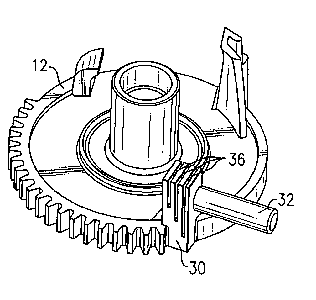
[0016]In the ETC 10, a first gear 12 is mounted in a gear housing 14. The first gear may be mounted in meshing engagement with one or more additional gears as required by the particular controller design being employed. For example, in the embodiment of FIG. 1, first gear 12 may be placed in meshing engagement with a second gear 16 which is coaxially mounted to a third gear 18 mounted in meshing engagement with a fourth gear 20. A shaft (not shown) extends from the center 12a of the first gear 12 for attaching to and controlling the movement of a component (not shown) such as a throttle valve blade, for example.

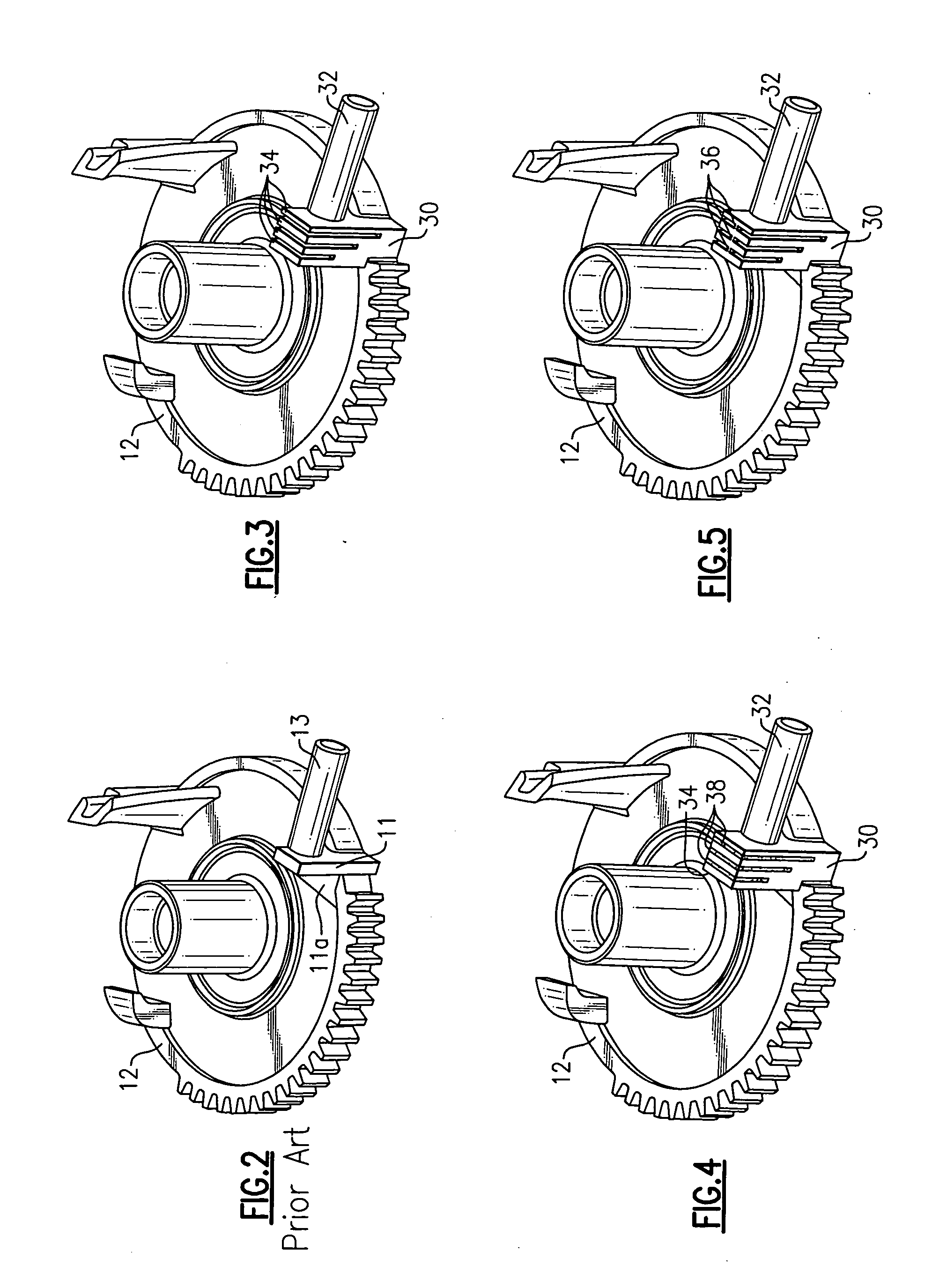
[0017]Referring to FIG. 2, a prior art gear stop 11 having ...


PUM


Abstract

A rotational speed damper operable to dampen the speed of a gear by gradually decreasing the rotational velocity and angular acceleration of the gear over a time period beginning at the time the damper contacts the gear stop and ending at the time the gear reaches its first stopping point.

Description

TECHNICAL FIELD OF THE INVENTION[0001]The present invention relates to gear control in a mechanical or electromechanical assembly such as a controller or actuator, for example.BACKGROUND OF THE INVENTION[0002]Many mechanical and electromechanical controllers and actuators include a gear or gear trains as part of their control mechanism design. Examples of such gear driven controllers and actuators include electronic throttle controls (ETCs) and actuators for controlling the opening and closing of a valve in a vehicle intake manifold. In their typical operating environment, these components are subject to frequent and abrupt stopping movements when reaching their stopping points which subject the gears and surrounding components to high stresses that can result in a breakdown of the gear teeth and failure of the part. While various attempts have been made to dampen the abrupt stopping movement of the gear, these attempts usually involve the addition of separately mounted components w...

Claims


Application Information

Patent Timeline
Patent Type & Authority Applications(United States)
IPC IPC(8): B60W10/10B60W10/18
CPCF02D9/107F16H2019/008F16H19/001
Inventor GARRICK, ROBERT D.GUTIERREZ, CARLOS A.
Owner DELPHI TECH INC
Why Eureka
Try Eureka