
Tuner device

a technology for tuning devices and radio receivers, which is applied in the direction of continuous tuning, resonance circuit tuning, casings/cabinets/drawers details, etc., can solve the problems of not meeting the user's need to effectively utilize surplus space, the difficulty of vertically installing the tuner module on the main surface of the main substrate, and not revealing materials

Inactive Publication Date: 2008-03-20
MITSUMI ELECTRIC CO LTD
View PDF8 Cites 6 Cited by
  • Summary
  • Abstract
  • Description
  • Claims
  • Application Information

AI Technical Summary

Benefits of technology

The invention provides a tuner device that can be installed on a main surface of a substrate, even if the substrate is made of an unsolderable material. This is achieved by using a metallic case made of an unsolderable material, with a bracket made of a solderable material fixed to the metallic case. The bracket holds the tuner module on the surface of the substrate. The invention also provides a tuner device with a printed circuit board and connector pins, even if the metallic case is made of an unsolderable material. The tuner device can be easily installed and maintained.

Problems solved by technology

However, since aluminum is an unsolderable material, it is difficult to vertically install the tuner module on the main surface of the main substrate.
As a result, the user's need of utilizing effectively the surplus space can not be satisfied.
Patent Document 3 only proposes a tuner case that can be used as a vertical fixation (vertical arrangement) as well as a face-down fixation (horizontal arrangement), but does not disclose any materials for use in the metallic case (shield case).
In this case, stress on a soldered portion, originating from vibration or tensile cannot be readily reduced by simply soldering between the end portion of the coaxial cable and the RF input portion.
However, it is difficult to compactly pack the tuner device due to an obstacle of the coaxial cable.
In this case, the coaxial cable is apt to be dropped into the solder deep bath by mistake.

Method used


Image

  • Tuner device
  • Tuner device
  • Tuner device

Examples


Embodiment Construction

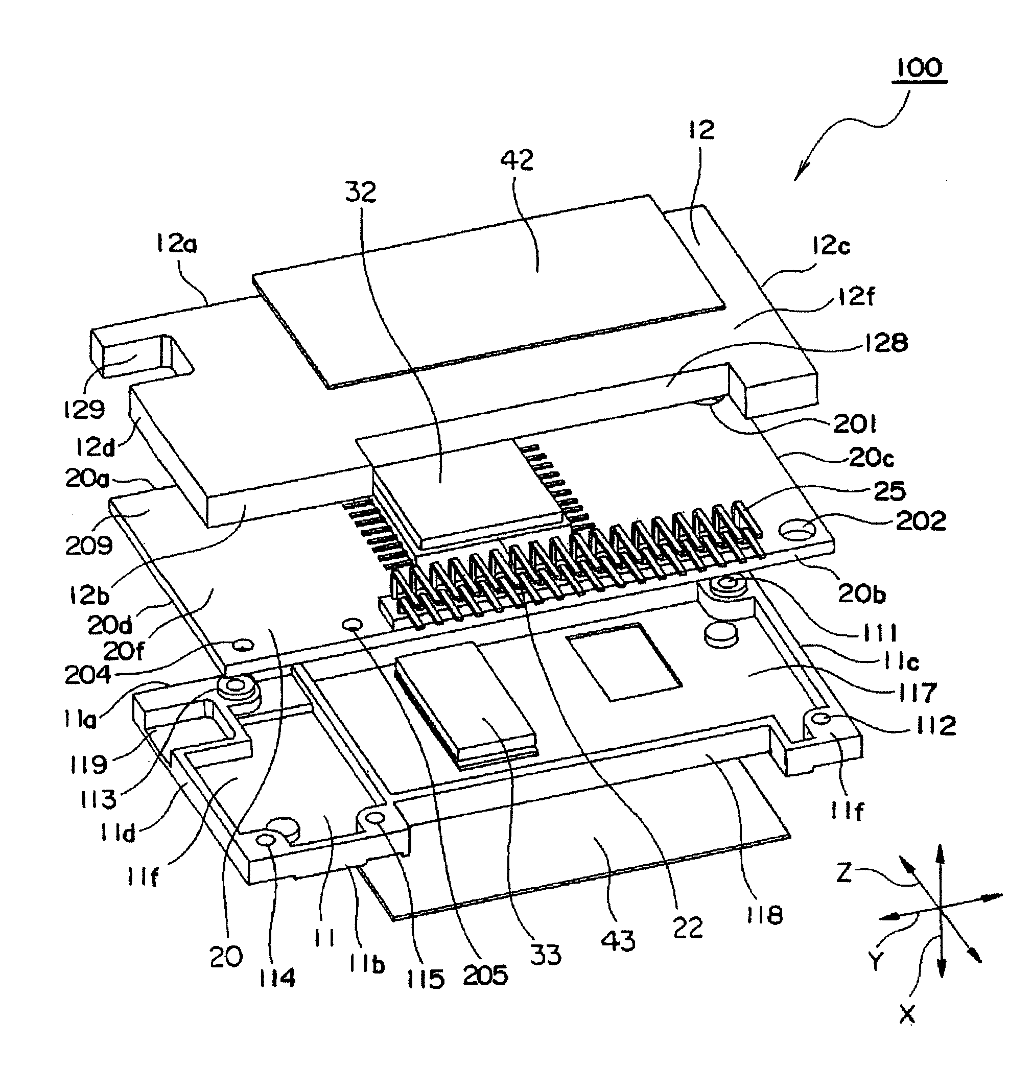
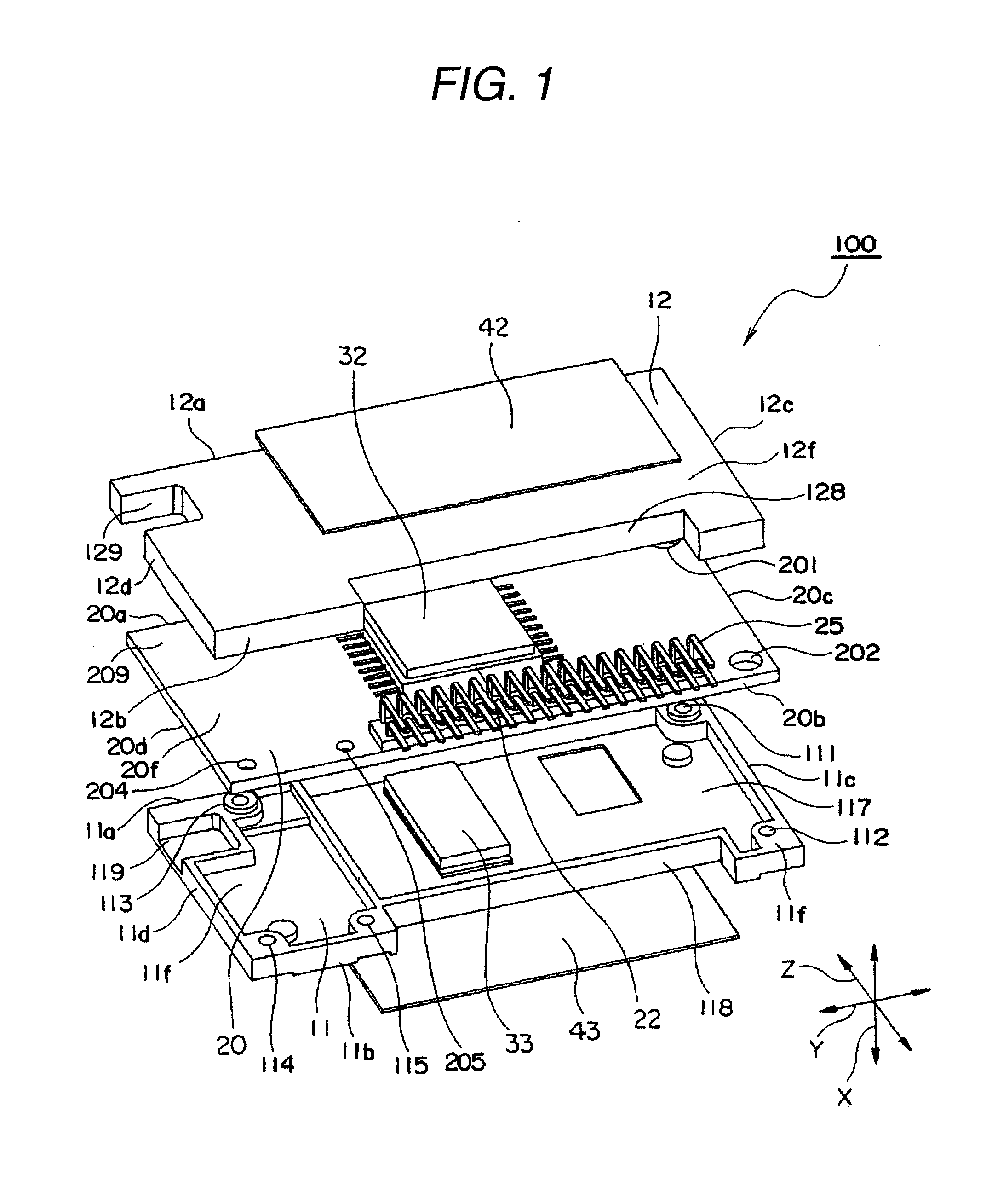
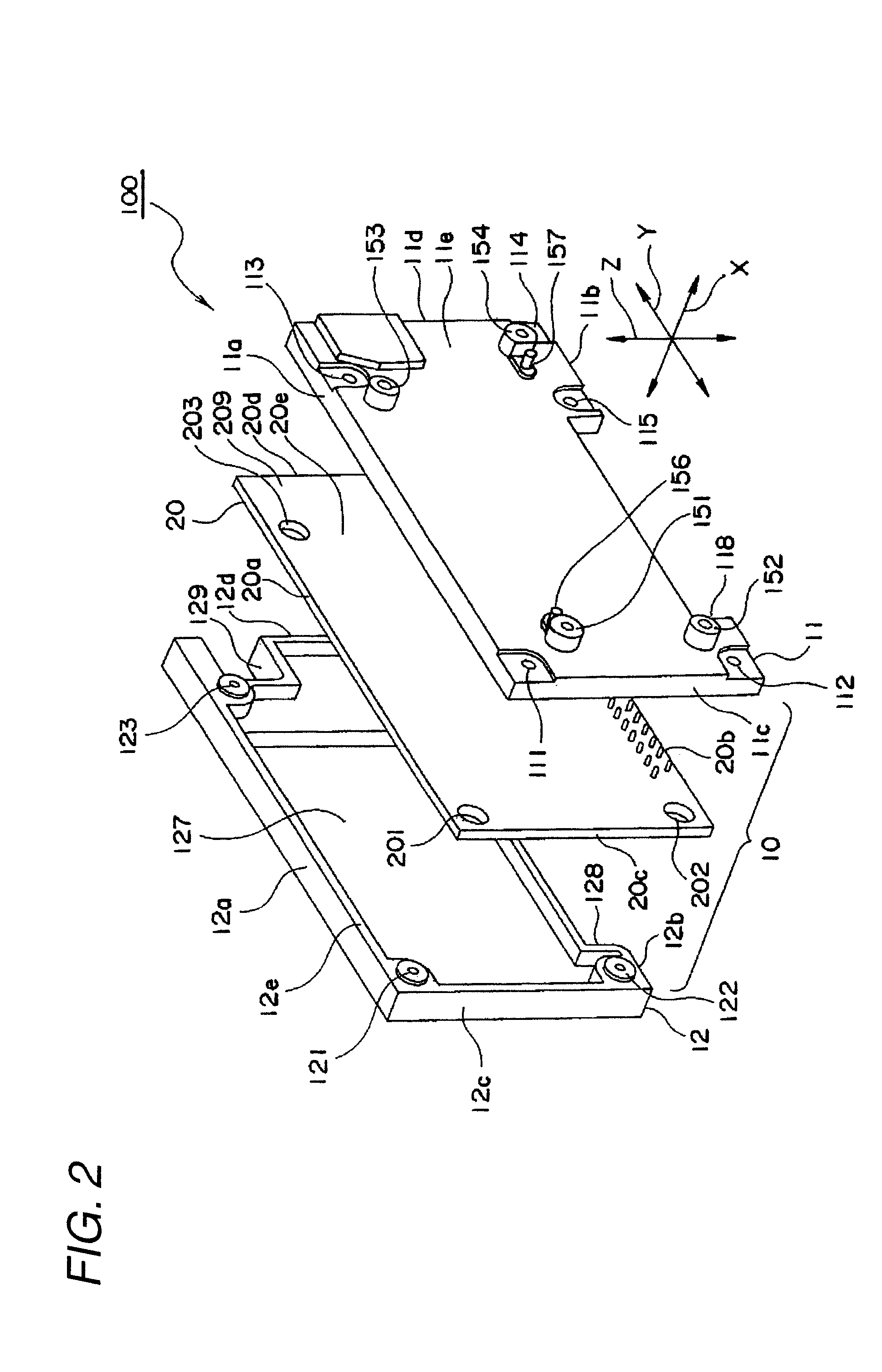
[0037]Exemplary embodiments of the invention will be described in greater detail hereinafter with reference to the drawings.

[0038]First, a tuner module 100 employing the tuner device according to the invention will be described herein below with reference to FIGS. 1 to 3. In FIGS. 1 to 3, an X-direction represents a front-rear direction (depth direction, thickness direction), a Y-direction represents a right-left direction (transverse direction, width direction), and a Z-direction represents an upper-lower direction (height direction).

[0039]FIGS. 2 and 3 show a case that a tuner unit, a demodulator, a sound decoder unit, a data decoder unit and controller for controlling them, among the elements constituting the vehicle digital radio receiver are mounted on one printed circuit board, and the printed circuit board is accommodated in the metallic case (shield case). Such a configuration is referred to as a tuner module.

[0040]In FIG. 2, the tuner module 100 includes a metallic case (sh...


PUM


Abstract

A tuner device comprising: a tuner module, disposed on a surface of a substrate and comprising: a circuit component adapted to demodulate a signal received from an antenna device; a printed circuit board mounted with the circuit component and a plurality of connector pins extending perpendicular to the surface of the substrate; and a metallic case, housing the printed circuit board so as to shield the circuit component, and made of an unsolderable material; and a bracket made of a solderable material, and fixed to the metallic case while holding the tuner module so as to dispose the tuner module on the surface of the substrate.

Description

BACKGROUND[0001]1. Technical Field[0002]The present invention relates to a tuner device for a radio receiver, and more in particular, to a tuner device suitable for a vehicle digital radio receiver for receiving a radio wave transmitted from a satellite (hereinafter, referred to as satellite wave) or an radio wave transmitted from an earth station (hereinafter, referred to as terrestrial wave) so as to listen to digital radio broadcasting.[0003]2. Related Art[0004]In recent, digital radio receivers receiving a satellite wave or a terrestrial wave so as to listen to digital radio broadcasting have been developed and put into practical use in the United States. In general, the digital radio receivers can be mounted in a mobile object such as a vehicle to receive the radio wave in the frequency band of about 2.3 GHz for listening to the radio broadcasting. That is, the digital radio receivers are radio receivers for hearing the mobile broadcasting. Since the frequency of the reception ...

Claims


Application Information

Patent Timeline
Patent Type & Authority Applications(United States)
IPC IPC(8): H05K5/02
CPCH05K9/006
Inventor INABA, TOSHIHIKOSUZUKI, TAKUMISATO, KYUICHI
Owner MITSUMI ELECTRIC CO LTD
Learn More