Radar apparatus
- Summary
- Abstract
- Description
- Claims
- Application Information
AI Technical Summary
Benefits of technology
Problems solved by technology
Method used
Image

Examples
Embodiment Construction
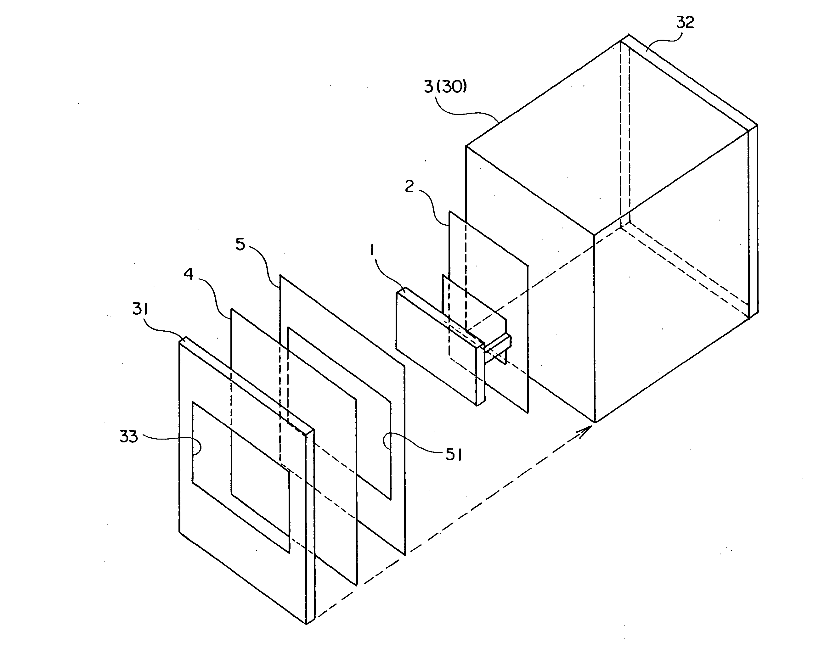
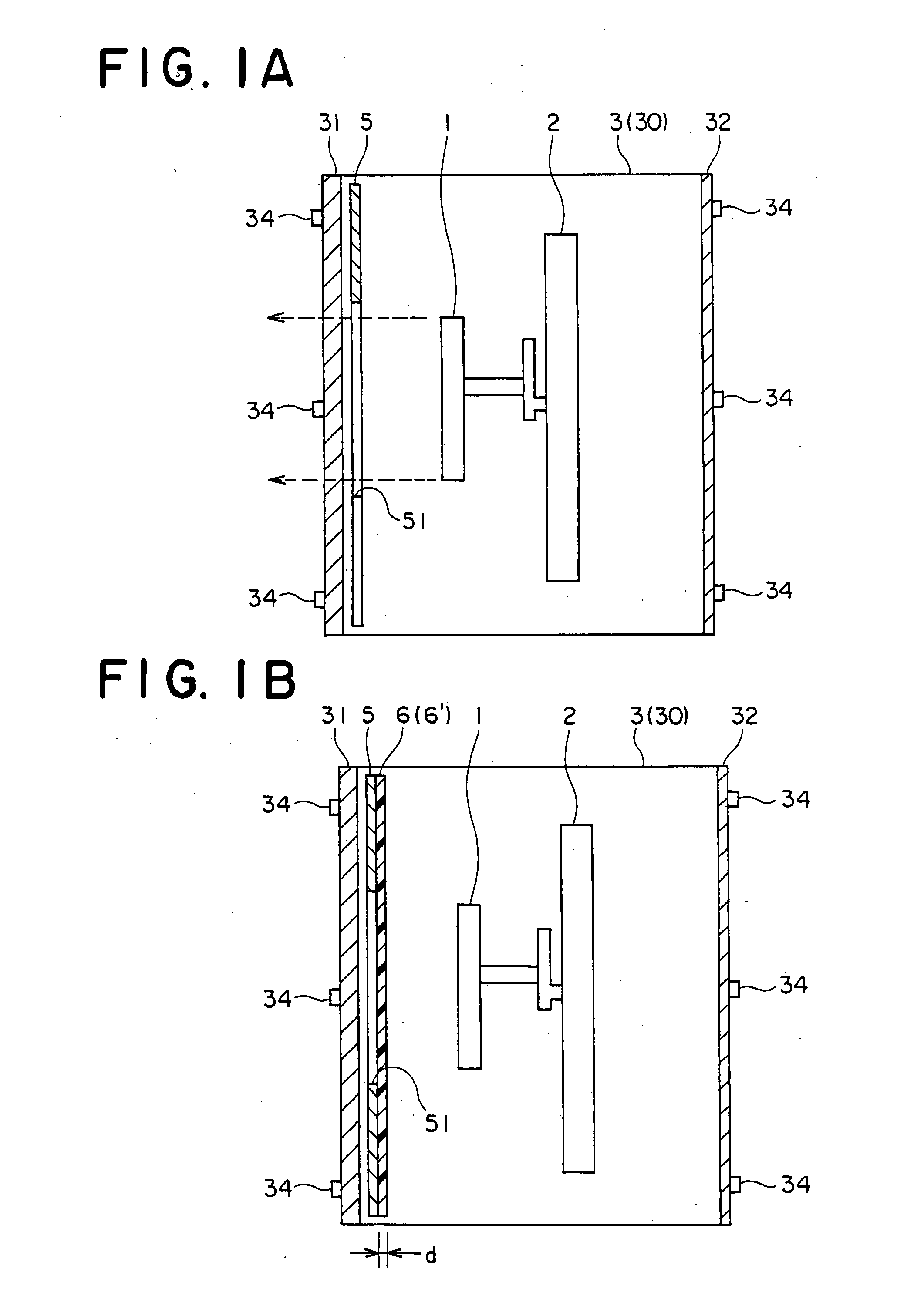
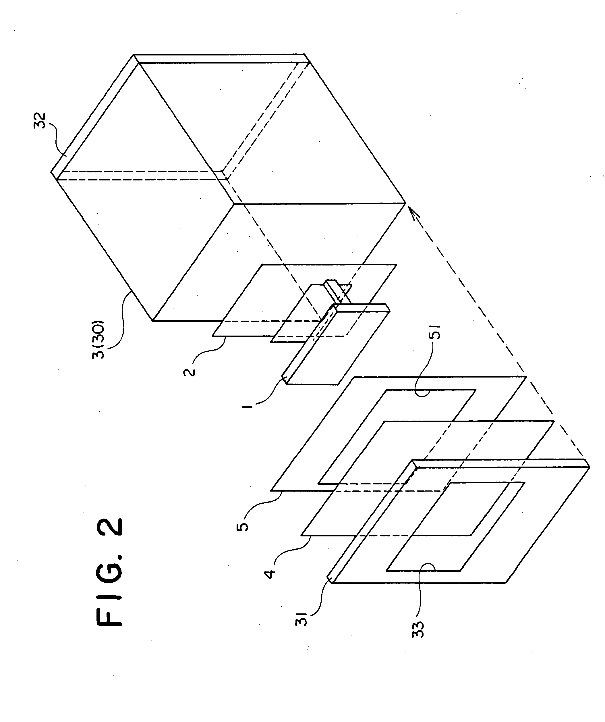
[0045]FIGS. 1A, 2, and 3 are diagrams of a radar apparatus, and show an example of a structure of a radar apparatus of the present invention. FIG. 1A shows a schematic structure of a partial section of the radar apparatus of the present invention. FIG. 2 shows a disassembled perspective view of the radar apparatus of the present invention. FIG. 3 shows a disassembled side view of the radar apparatus of the present invention. FIG. 4 is a diagram showing a structure of a shielding plate.
[0046] The radar apparatus of the present invention includes, as shown in FIGS. 1 to 4, a radar 1 employing millimeter wave, a signal processing circuit board 2, a housing 3, a radome (a protection plate or a cover) 4, and a shielding plate (a radio wave shielding plate) 5. The radar apparatus of the present invention is used as an object (or obstacle) sensor, for example.
[0047] The radar apparatus (the obstacle sensor) in this example transmits millimeter wave from the radar 1 to a reflector (a refl...
PUM
 Abstract
Description
Claims
Application Information
 - R&D Engineer
- R&D Manager
- IP Professional
- Industry Leading Data Capabilities
- Powerful AI technology
- Patent DNA Extraction
Browse by: Latest US Patents, China's latest patents, Technical Efficacy Thesaurus, Application Domain, Technology Topic.
© 2024 PatSnap. All rights reserved.Legal|Privacy policy|Modern Slavery Act Transparency Statement|Sitemap