Thermal printer

Inactive Publication Date: 2008-03-20
SEIKO INSTR INC
View PDF5 Cites 23 Cited by
  • Summary
  • Abstract
  • Description
  • Claims
  • Application Information

AI Technical Summary

Benefits of technology

[0018]As a result, the swing arm is swung with the result that the platen roller is spaced apart from a printing surface of the thermal head, and at the same time the receiving portion of the roll-formed thermal paper can be opened. Thus, a recovering operation of a paper jam or an exc...

Problems solved by technology

However, in the thermal printer disclosed in Patent Document 1, it is necessary to operate the release lever provi...

Method used


Image

  • Thermal printer
  • Thermal printer
  • Thermal printer

Examples


Embodiment Construction

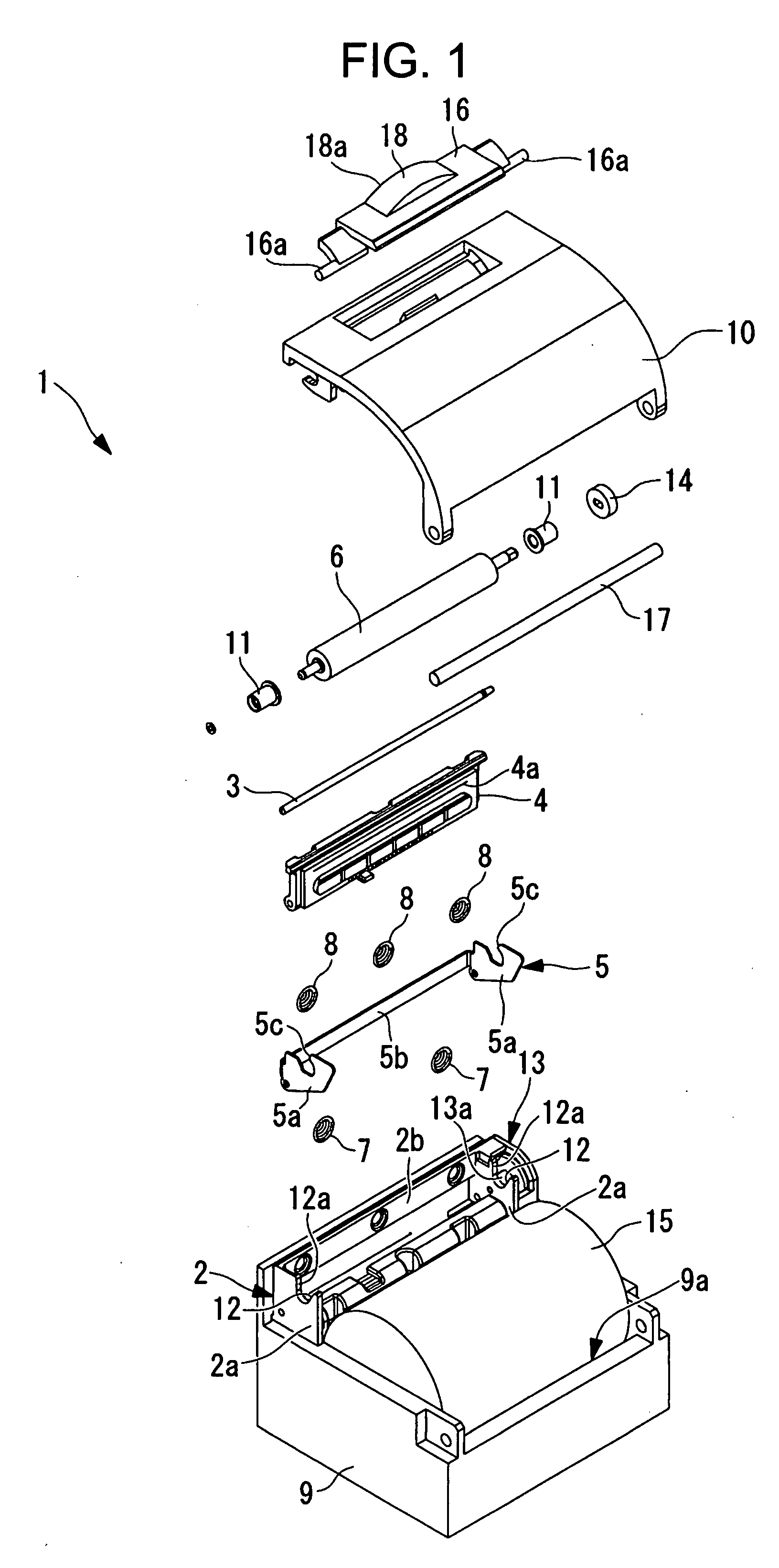
[0026]Referring to FIGS. 1 to 5, a thermal printer 1 according to an embodiment of the present invention will be described below.

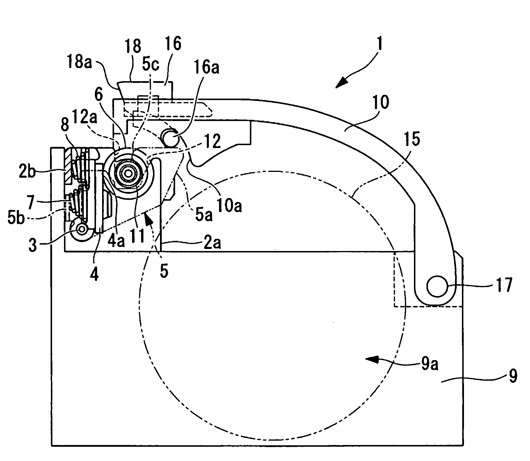
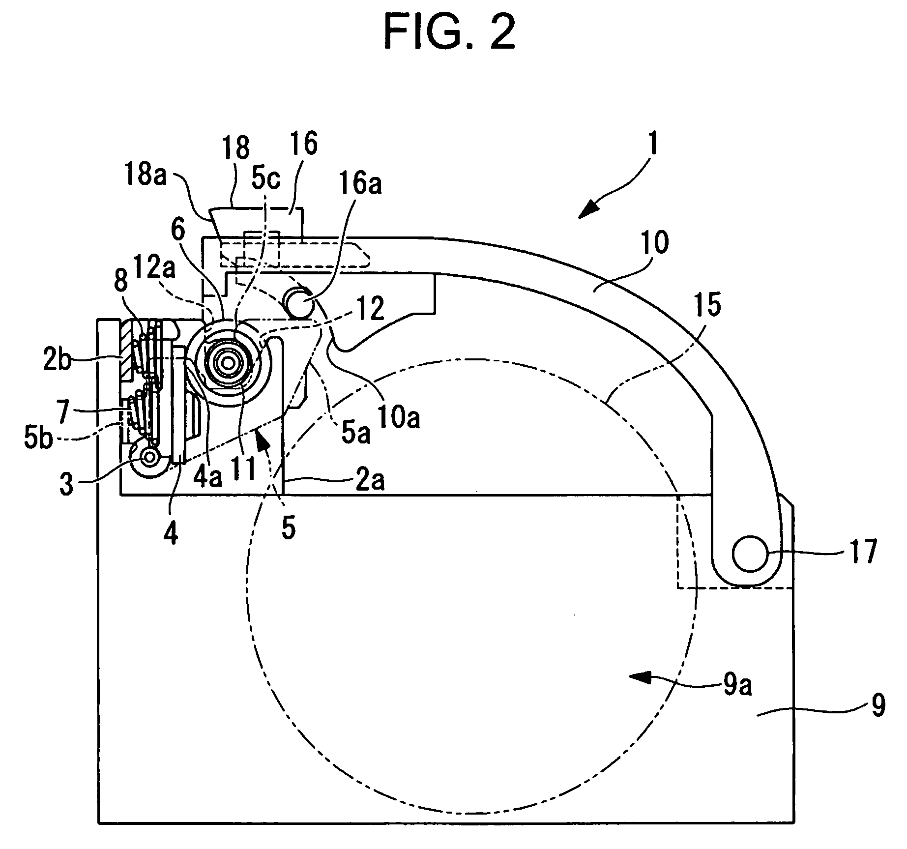
[0027]As shown in FIG. 1, the thermal printer 1 of the embodiment includes: a main body frame 2; a thermal head 4 and a lock arm 5 swingably mounted to a coaxial shaft 3 of the main body frame 2; a platen roller 6 supported by the lock arm 5; first springs 7, for biasing the platen roller 6 to the thermal head 4 side; and second springs 8 for biasing the thermal head 4 to the platen roller 6 direction. The thermal printer 1 further includes a case main body 9 to which the main body frame 2 is fixed and a cover member 10 provided to the case main body 9.

[0028]The main body frame 2 is provided with side walls 2a for bridging the shaft 3 and a back surface coupling plate portion 2b for coupling the side walls 2a. The side walls 2a of the main body frame 2 are provided with notches 12, respectively, for receiving a shaft bearing 11 (described later) of the pla...


PUM


Abstract

There is provided a thermal printer (1) including: a main body frame (2); a thermal head (4) mounted to the main body frame (2); a platen roller (6) disposed to be opposed to a printing surface (4a) of the thermal head (4), for sandwiching a thermal paper (15) with the thermal head (4) to feed the thermal paper (15); a lock arm (5) swingably mounted to the main body frame (2), for locking the platen roller (6) with the main body frame (2) by pressing a shaft bearing (11) which rotatably supports the platen roller (6) against the thermal head (4); a swing arm (10) that supports the shaft bearing (11) of the platen roller (6), and swings between a lock position by the lock arm (5) and a release position apart from the lock arm (5); and a lever (16) movably provided to the swing arm (10), for releasing a locked state of the platen roller (6) by the lock arm (5) by an external force applied to a force point (18), in which a direction in which the force point (18) of the lever (16) moves when the locked state by the lock arm (5) is released is same as a swinging direction of the swing arm (10).

Description

BACKGROUND OF THE INVENTION[0001]1. Field of the Invention[0002]The present invention relates to a thermal printer.[0003]2. Description of the Related Art[0004]As a conventional thermal printer, there is one disclosed in Patent Document 1.[0005]The thermal printer disclosed in Patent Document 1 includes a cover member for supporting a platen roller disposed to be opposed to a printing surface of a thermal head. The cover member is locked by a lock arm in a state where the platen roller is close contact with the printing surface of the thermal head, so the cover member is locked with respect to a case main body.[0006]Further, by operating a release lever provided to the case main body, the lock arm is swung by the release lever to release a locked state of the platen roller with the result that the locked state of the cover member with respect to the case main body is released. The cover member whose locked state is released can swing with respect to the case member, so it is possibl...

Claims


Application Information

Patent Timeline
IPC IPC(8): B41J11/04
CPCB41J15/042
Inventor HIRAI, KIMITAKA
Owner SEIKO INSTR INC
Why Eureka
Try Eureka