Supercharge Your Innovation With Domain-Expert AI Agents!

Control system using a mini slot signal in a passive optical network

a control system and optical network technology, applied in the field of control system using a mini slot signal in a passive optical network, can solve the problem of not being able to monitor and control the receiving state of the regular cell and the mini slot signal individually

Inactive Publication Date: 2008-03-20
MITSUBISHI ELECTRIC CORP
View PDF17 Cites 8 Cited by
  • Summary
  • Abstract
  • Description
  • Claims
  • Application Information

AI Technical Summary

Benefits of technology

The invention solves problems in the related art by controlling an apparatus in a method using a mini slot signal in a passive optical network. This allows for dynamic bandwidth assignment without interrupting the communication of regular cells and child stations. The control system uses a maintenance signal for each child station to control state transition in dynamic bandwidth assignment. The invention also allows for individual monitoring of mini slot signals in each child station. The technical effects of the invention include improved network efficiency and reliability.

Problems solved by technology

Therefore, it is impossible to monitor and control a receiving state of the regular cell and the mini slot signal individually.

Method used


Image

  • Control system using a mini slot signal in a passive optical network
  • Control system using a mini slot signal in a passive optical network
  • Control system using a mini slot signal in a passive optical network

Examples


embodiment 1

[0043] Embodiments of this invention are explained.

[0044] A maintenance signal for a mini slot signal and an operation of this invention are explained by FIG. 1 and FIG. 2.

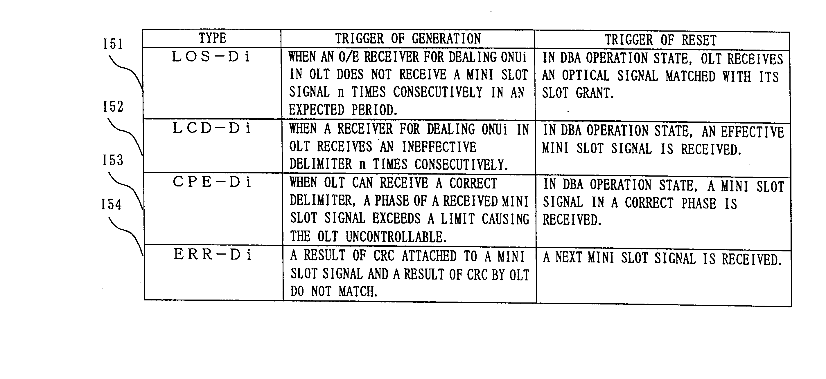
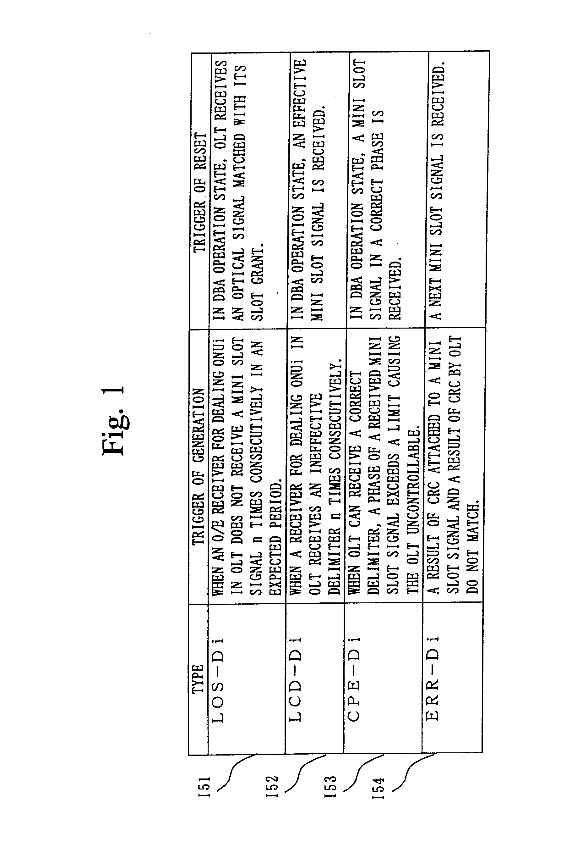
[0045] In FIG. 1, as types of the maintenance signal, failure of receiving a mini slot signal (LOS-Di) 151, out-of-synchronization of the mini slot signal (LCD-Di) 152, error in a phase of receiving the mini slot signal (CPE-Di) 153, error in a block of the mini slot signal (ERR-Di) 154 are provided besides the maintenance signal of the regular cell.

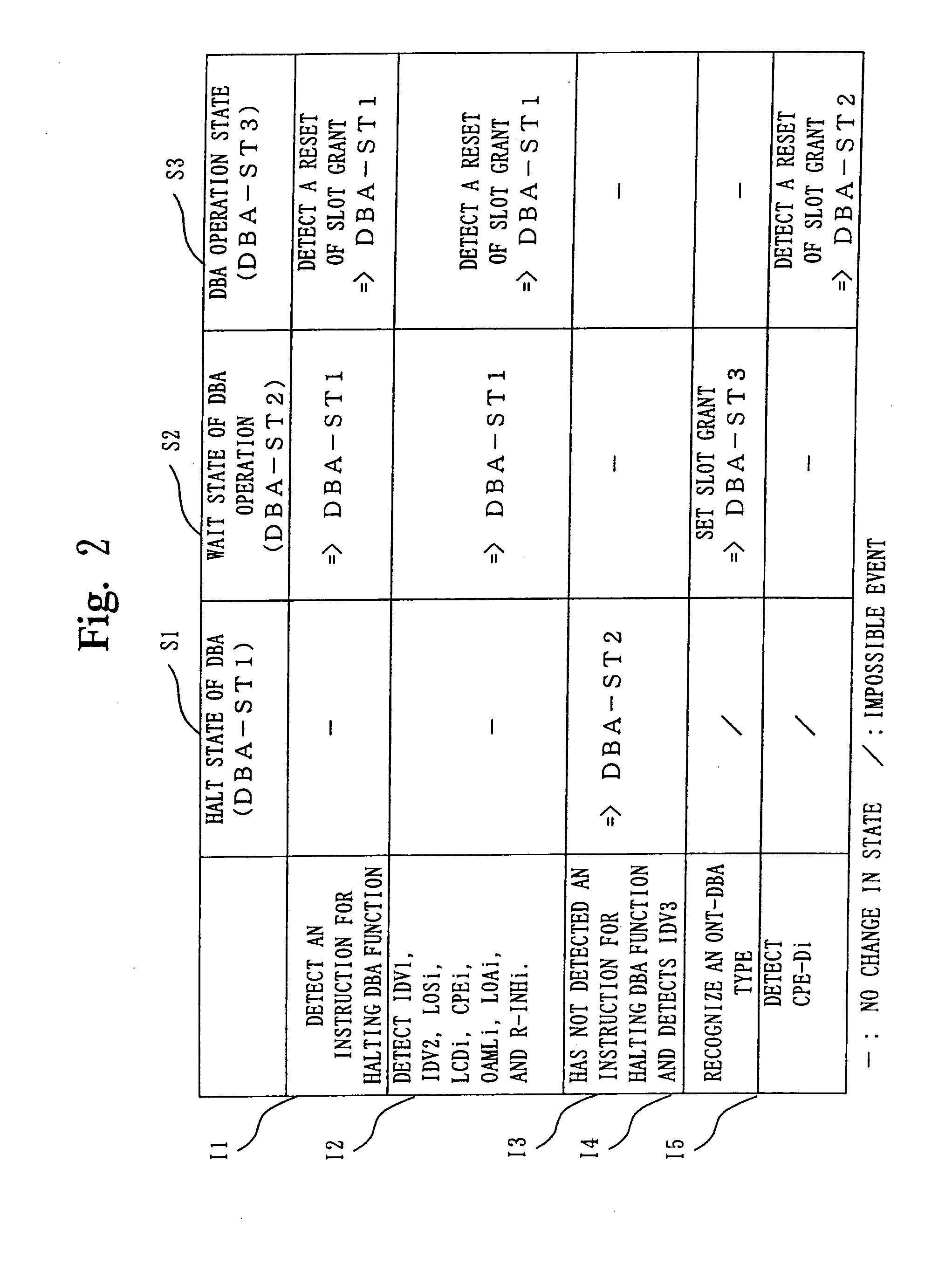
[0046]FIG. 2 shows a state transition table for corresponding the maintenance signals for the mini slot signal described in FIG. 1 to a state of controlling the ONU individually by the OLT. An operation of this invention is explained by FIG. 1 and FIG. 2. As illustrated in FIG. 2, an individual ONU dealing unit 106 and a DBA controller 109, which are provided additionally, manage and control by performing the dynamic bandwidth assignment (DBA) for upstream correspon...


PUM


Abstract

According to an aspect of this invention, dynamic bandwidth assignment (DBA) can be performed without interrupting communication of a regular cell and interfering with communication between child stations. In a passive optical network including a parent station and a plurality of child stations, a maintenance signal for a mini slot signal is provided. Each of the child stations sends a corresponding maintenance signal if necessary, and the parent station controls state transition by using the maintenance signal concerning on the mini slot signal for each of the child stations. By controlling the state transition, the dynamic bandwidth assignment can be performed.

Description

CROSS-REFERENCE TO RELATED APPLICATIONS [0001] The present divisional application claims the benefit of priority under 35 U.S.C. §120 to application Ser. No. 10 / 147,885, filed on May 20, 2002, and under 35 U.S.C. §119 from Japanese Application No. 2001-151302, filed on May 21, 2001, the entire contents of both are hereby incorporated herein by reference.BACKGROUND OF THE INVENTION [0002] 1. Field of the Invention [0003] This invention relates to a maintenance signal corresponding to a mini slot signal in a slot according to international standard ITU-T G.983.1 regulating a physical interface in a PON (Passive Optical Network) and a method for controlling a state in dynamic bandwidth assignment (DBA) for upstream by using the mini slot signal. [0004] 2. Description of the Related Art [0005]FIG. 3 illustrates an example of a configuration of a system in the PON including a DBA function, in which an OLT (optical line terminator—parent station) 101 and a plurality of ONU's (optical netw...

Claims


Application Information

Patent Timeline
Patent Type & Authority Applications(United States)
IPC IPC(8): H04B7/212H04J14/08H04J3/16H04L12/44H04B10/272H04J3/14H04Q11/00
CPCH04J3/14H04J3/1694H04Q2011/0086H04Q11/0067H04Q2011/0064H04Q11/0062
Inventor ASASHIBA, YOSHIHIROYOSHIDA, TOSHIKAZUMUKAI, HIROAKIKOZAKI, SEIJI
Owner MITSUBISHI ELECTRIC CORP
Features
  • R&D
  • Intellectual Property
  • Life Sciences
  • Materials
  • Tech Scout
  • Unparalleled Data Quality
  • Higher Quality Content
  • 60% Fewer Hallucinations
Learn More