Fusing device and image forming apparatus having the same

a technology of fusing device and image forming apparatus, which is applied in the direction of electrographic process apparatus, instruments, printing, etc., can solve the problems of increased cost of added components, reduced reliability of high pressure release function, and additional costs to maintain reliability

Active Publication Date: 2008-03-20
HEWLETT PACKARD DEV CO LP
View PDF4 Cites 24 Cited by
  • Summary
  • Abstract
  • Description
  • Claims
  • Application Information

AI Technical Summary

Benefits of technology

[0014]According to an aspect of the invention, a fusing device of an image forming apparatus designed in order to achieve the above and / or other aspects and advantages includes a fusing unit having a heating roller and a pressure roller which contact with other and rotate together, a cover which opens and closes the fusing unit, and a pressure and release unit, including a rotational shaft, and a member rotatable about the rotational shaft and having a pressuring part that transmits pressure to the pressure roller in a direction of the heating roller if the cover is shut and a pressured part pressured by the cover and disposed farther than the pressuring part from the rotational shaft.

Problems solved by technology

However, if a separate power source and position detection sensor are used as described above, these added components increase costs, and if the system suddenly halts during operation (for example, due to power being cut or a lightning strike), the reliability of the high pressure release function also drops, or additional costs are required to maintain reliability.
However, a problem with this second suggested method is that the reliability of the high pressure release function may drop if the configuration changes due to changes in the lever or cam caused by the high temperature of the heating roller or wear and tear of the cam parts.

Method used


Image

  • Fusing device and image forming apparatus having the same
  • Fusing device and image forming apparatus having the same
  • Fusing device and image forming apparatus having the same

Examples


Embodiment Construction

[0028]Reference will now be made in detail to the present embodiments of the present invention, examples of which are illustrated in the accompanying drawings, wherein like reference numerals refer to the like elements throughout. The embodiments are described below in order to explain the present invention by referring to the figures.

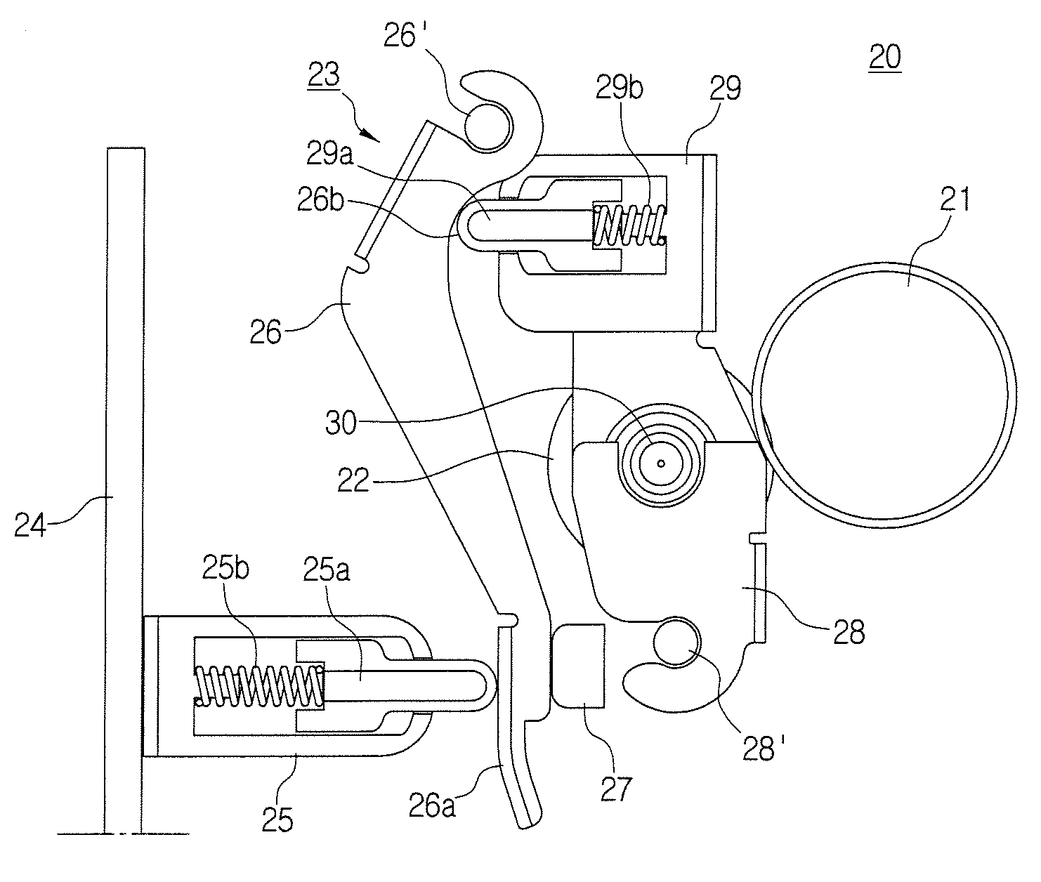
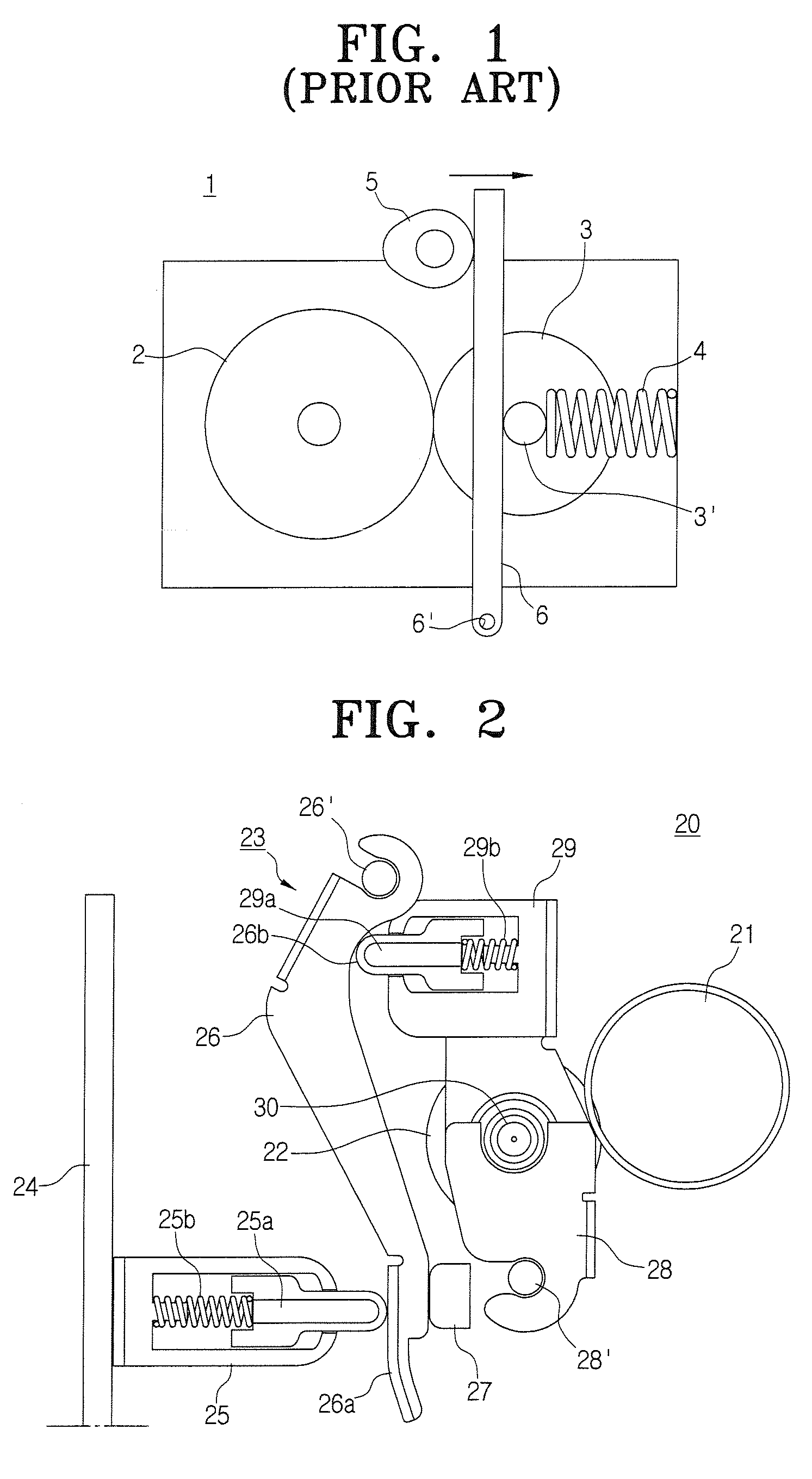
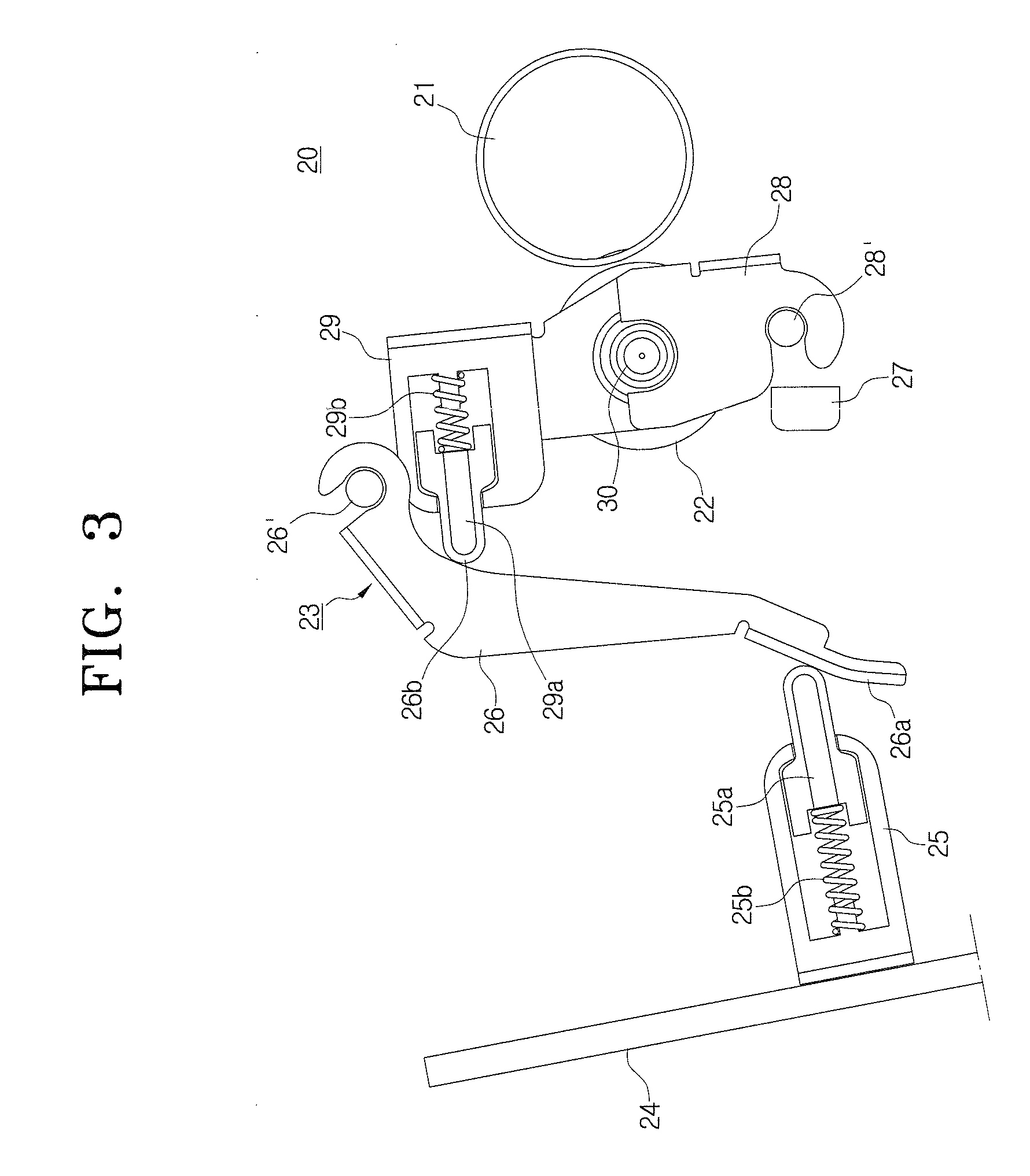
[0029]FIG. 2 shows an embodiment of the fusing device according to an embodiment of the present invention. The fusing device 20 of FIG. 2 includes a heating roller 21 which provides heat, and which a recording medium having a developed image passes by; a pressure roller 22, which faces the heating roller and provides pressure; and a pressure and release unit 23, also known as a lever unit, which provides pressure to and releases the pressure from the above pressure roller 21. It is understood that the recording medium may be various types of recording media, such as paper, transparency sheets, etc.

[0030]The pressure and release unit 23 is formed as a t...


PUM


Abstract

A fusing device of an image forming apparatus which applies principles of leverage, and an image forming apparatus containing such a device. The fusing device includes a fusing unit having a heating roller and a pressure roller facing each other and which rotate together, a cover which opens and closes the fusing unit, and a pressure and release unit, one end of which is rotatably fixed to a rotating shaft, the pressure and release unit containing a member having a pressuring unit which pressures the pressure roller towards the heating roller when the cover opens and shuts, and a pressured part, which is farther from the rotating shaft than the pressuring part and which receives pressure from the cover.

Description

CROSS-REFERENCE TO RELATED APPLICATION[0001]This application claims the priority of Korean Patent Application No. 2006-89822 filed on Sep. 15, 2006, in the Korean Intellectual Property Office, the disclosure of which is incorporated herein by reference.BACKGROUND OF THE INVENTION[0002]1. Field of the Invention[0003]Aspects of the present invention relate to a fusing device of an image forming apparatus, and more specifically, to a device which releases the pressure between rollers used in fusing an electrostatic latent image onto print material.[0004]2. Description of the Related Art[0005]Image forming apparatuses generally include a paper feed device which picks up paper from a feeding tray and feeds the paper along a feed path, a developing device which applies developing materials to an electrostatic latent image and develops the image, a transfer device which transfers the developed image onto the paper, and a fusing device which fuses the developed image onto a surface of the p...

Claims


Application Information

Patent Timeline
Patent Type & Authority Applications(United States)
IPC IPC(8): G03G15/20
CPCG03G2221/1639G03G15/2035G03G21/1685G03G2221/169G03G15/2064G03G2215/2025
Inventor CHANG, WOONG-JAEBAE, SEA-CHUL
Owner HEWLETT PACKARD DEV CO LP
Why Eureka
Try Eureka