Vehicle drive force distribution control system

a technology of drive force and control system, which is applied in the direction of electric devices, instruments, transportation and packaging, etc., can solve the problems of unreproducible variation in relationship, driver discomfort,

Inactive Publication Date: 2008-03-20
NISSAN MOTOR CO LTD
View PDF3 Cites 47 Cited by
  • Summary
  • Abstract
  • Description
  • Claims
  • Application Information

AI Technical Summary

Benefits of technology

[0006] When a vehicle is turning, a tire lateral force acts on each of the wheels depending on a skid angle thereof. Since the drive force and the tire lateral force have a non-linear relationship, the tire lateral force varies in a non-linear fashion with respect to the drive force acting on the wheel when it is corrected by applying the prior art drive force distribution control system.

Problems solved by technology

As a result a variation in the tire lateral force of a wheel having a corrected drive force may bring about an unreproducible variation in the relationship between a vehicle lateral force generated by the tire lateral forces and a yaw moment about the center of gravity of the vehicle.
Such an unreproducible variation may cause a driver of the vehicle to feel discomfort.

Method used


Image

  • Vehicle drive force distribution control system
  • Vehicle drive force distribution control system
  • Vehicle drive force distribution control system

Examples


second embodiment

[0236] this invention will now be described.

[0237] The components of the vehicle according to this embodiment are identical to those of the first embodiment. In this embodiment, control processing partially differs from that of the first embodiment. With respect to the components and the steps that are identical to those of the first embodiment, the description is herein omitted.

[0238] Referring to FIG. 20, the steps S10-S100, S120, and S130 are identical to those of the first embodiment. In this embodiment, a step S500 replaces the step S110 of the first embodiment.

[0239] In the step S500, the controller 8 selects a set of the wheel drive force command values from among the sets of the wheel drive forces obtained in the step S100 by applying the following methods.

[0240] As a first method, when the flag flgy is at unity, a set of the wheel drive forces is selected from among the sets of the wheel drive forces Fxyf(n), Fxy3(n), and Fxy4(n) obtained in the step S100 such that a sum...

first embodiment

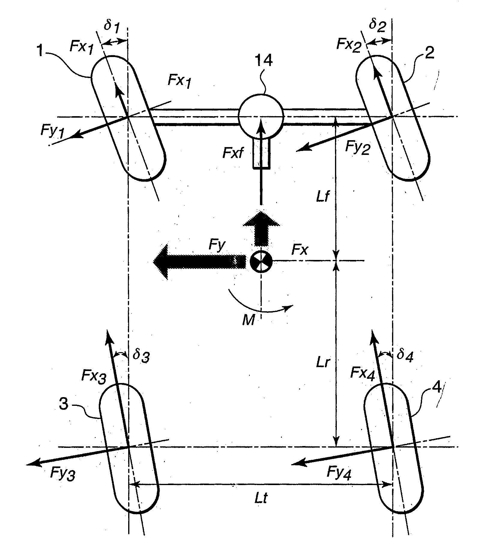
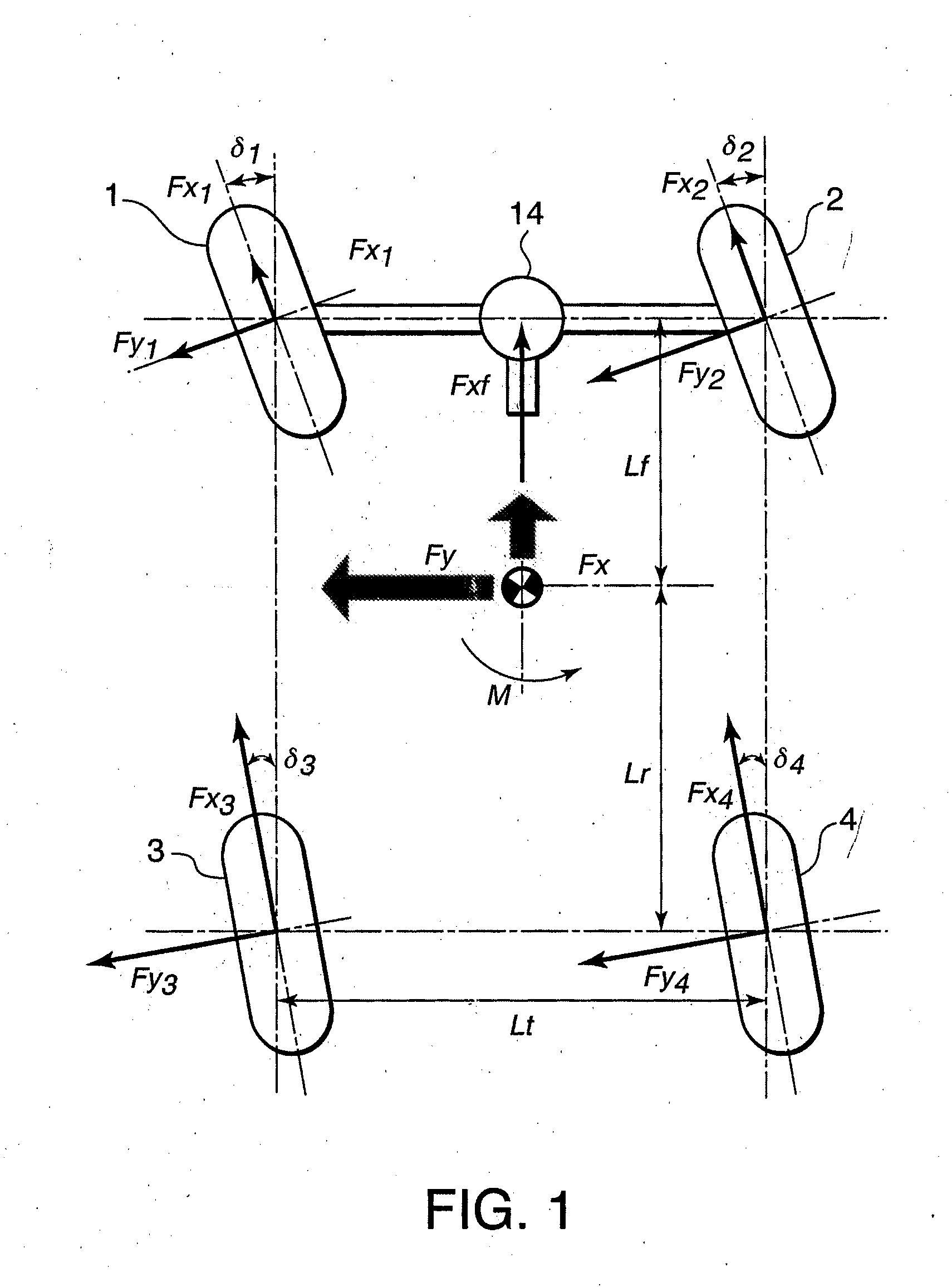
[0280] In the first embodiment, this invention is applied to a vehicle in which the front wheels 1, 2, the right rear wheel 4, and the left rear wheel 3 are driven independently of each other. It is also possible to apply this invention to a vehicle in which the right front wheel 2, the left front wheel 1, and the rear wheels 3, 4 are driven independently of each other, by considering the wheel drive force characteristic of the rear wheels 3, 4 via the differential gear mechanism.

[0281] This invention can also be applied to a four-wheel drive vehicle in which the right front wheel 2 is driven by an electric motor 52, the left front wheel 1 is driven by an electric motor 51, the right rear wheel 4 is driven by an electric motor 54, and the left rear wheel 4 is driven by an electric motor 53, as shown in FIG. 21.


PUM


Abstract

A controller (8) controlling a drive force distributed to each wheel (1-4) of a vehicle sets dynamic drive force target values (Fxf**, Fx3**, Fx4**) to the wheels, and determines a variation amount target ratio related to variation amounts (ΔM, ΔFx, ΔFy) of a vehicle yaw moment (M), a vehicle front/aft force (Fx), and a vehicle lateral force (Fy) such that a vehicle behavior generated by the dynamic drive force target values does not vary. The controller (8) determines sets of the drive forces (Fxf(j, k), Fx3(j, k), Fx4(j, k)) realizing the variation amount target ratio, selects drive force command values from these sets such that each drive force command value is within a drive force limiting range, and controls a drive force regulating mechanism (20, 12, 13, 15,16) according to the selected drive force command values.

Description

FIELD OF THE INVENTION [0001] This invention relates to the control of drive force distributed to wheels in a four-wheel drive vehicle. BACKGROUND OF THE INVENTION [0002] JPH10-295004A published by the Japan Patent Office in 1998 discloses a drive force distribution control system for a four-wheel drive vehicle. The four-wheel drive vehicle includes a vehicle that drives a right rear wheel and a left rear wheel independently of each other while driving a right front wheel and a left front wheel via a differential gear, a vehicle that drives a right front wheel and a left front wheel independently of each other while driving a right rear wheel and a left rear wheel via a differential gear, and a vehicle that drives each of the four wheels independently. [0003] The prior art system corrects a drive force of each wheel so as not to cause a variation in a yaw moment acting on the vehicle body when a tendency for slippage or wheel lock is detected in a wheel or plural wheels, or in other...

Claims


Application Information

Patent Timeline
Patent Type & Authority Applications(United States)
IPC IPC(8): G06F19/00B60K6/52B60K6/54B60K17/356B60L50/16B60W10/06B60W10/08B60W10/10B60W20/00B60W30/00B60W30/02B60W30/045
CPCB60W2720/30B60W2720/14Y02T10/6286Y02T10/642B60K6/52B60K7/0007B60K17/356B60K23/0808B60L2240/423B60W10/04B60W10/06B60W10/08B60W10/18B60W30/045B60W2050/0028B60W2300/18B60W2520/14B60W2710/083Y02T10/6265B60L3/102Y02T10/62Y02T10/64B60W2540/18
Inventor YAMAGUCHI, ICHIRODEGUCHI, YOSHITAKA
Owner NISSAN MOTOR CO LTD
Why Eureka
Try Eureka