Dispensing Utensil

a technology for utensils and spoons, which is applied in the field of utensils, can solve the problems of unsuitable reuse, inability to close the container portion, and high manufacturing cost, and achieve the effects of reducing littering, reducing tampering with utensils, and facilitating us

Inactive Publication Date: 2008-03-27
SANDS INNOVATIONS
View PDF99 Cites 51 Cited by
  • Summary
  • Abstract
  • Description
  • Claims
  • Application Information

AI Technical Summary

Benefits of technology

[0012] A further advantage of the present invention is its ease of use. The first portion of the first wall means is openable about the hinge formed by the second wall means. This allows for easy one-handed operation and also retains the first portion on the utensil, which may reduce littering etc.
[0013] The failure zone between the first and second portions could be a thinner area of material, or could be weakened by other failure means such as perforations. Advantageously, this also contributes to increased tamper-proofing of the utensil, as it is readily apparent that the utensil has been opened.
[0014] In one embodiment the first portion of the first wall means is distal from the implement portion. This advantageously allows for some contents to be dispensed, and for the tool to then be used without dispensing further contents (e.g., to stir a half portion of sugar in coffee).
[0015] In another embodiment the first portion of the first wall means is a proximal of the implement portion. This advantageously allows for contents to be dispensed and the tool immediately to be used without reversing (e.g., to stir a full portion of sugar in coffee).
[0016] Preferably, an embodiment of the invention further includes a second cavity for storing dispensable contents and preferably dispensing of contents from the second cavity is independently operable in the same manner as the first cavity. This advantageously allows for provision of complementary contents such as pepper and salt, in separately controlled portions.
[0017] Preferably, the first portion of the first wall means is re-closable, optionally by a friction fit. Advantageously, this prevents spillage and allows for any remaining contents to be used at a later time.

Problems solved by technology

These dispensing spoons suffer one or more of the following disadvantages including being expensive to manufacture, not suitable for reuse, unable to reclose the container portion and aesthetically unappealing.

Method used


Image

  • Dispensing Utensil
  • Dispensing Utensil
  • Dispensing Utensil

Examples


Embodiment Construction

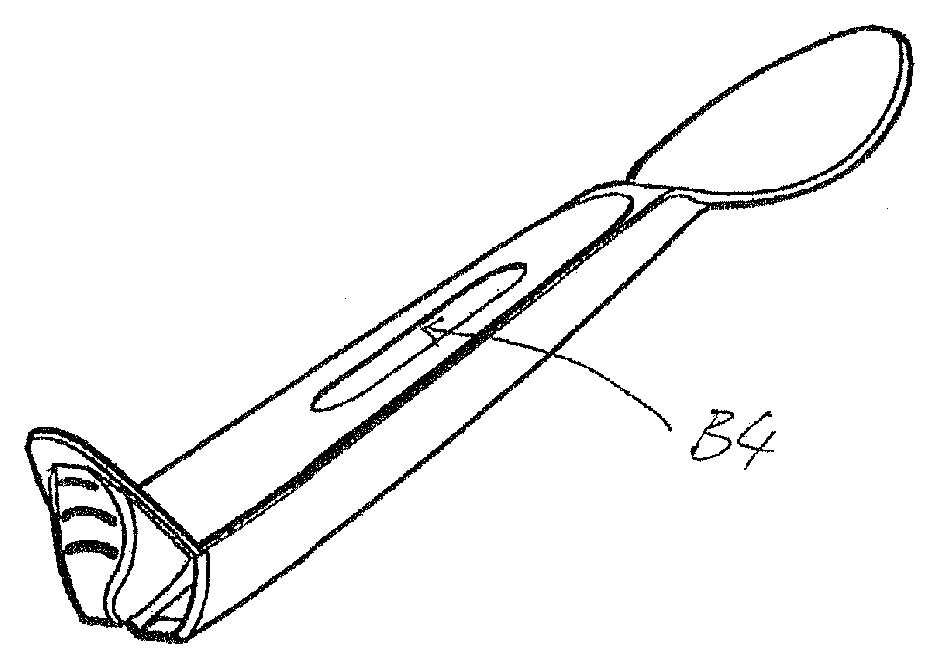
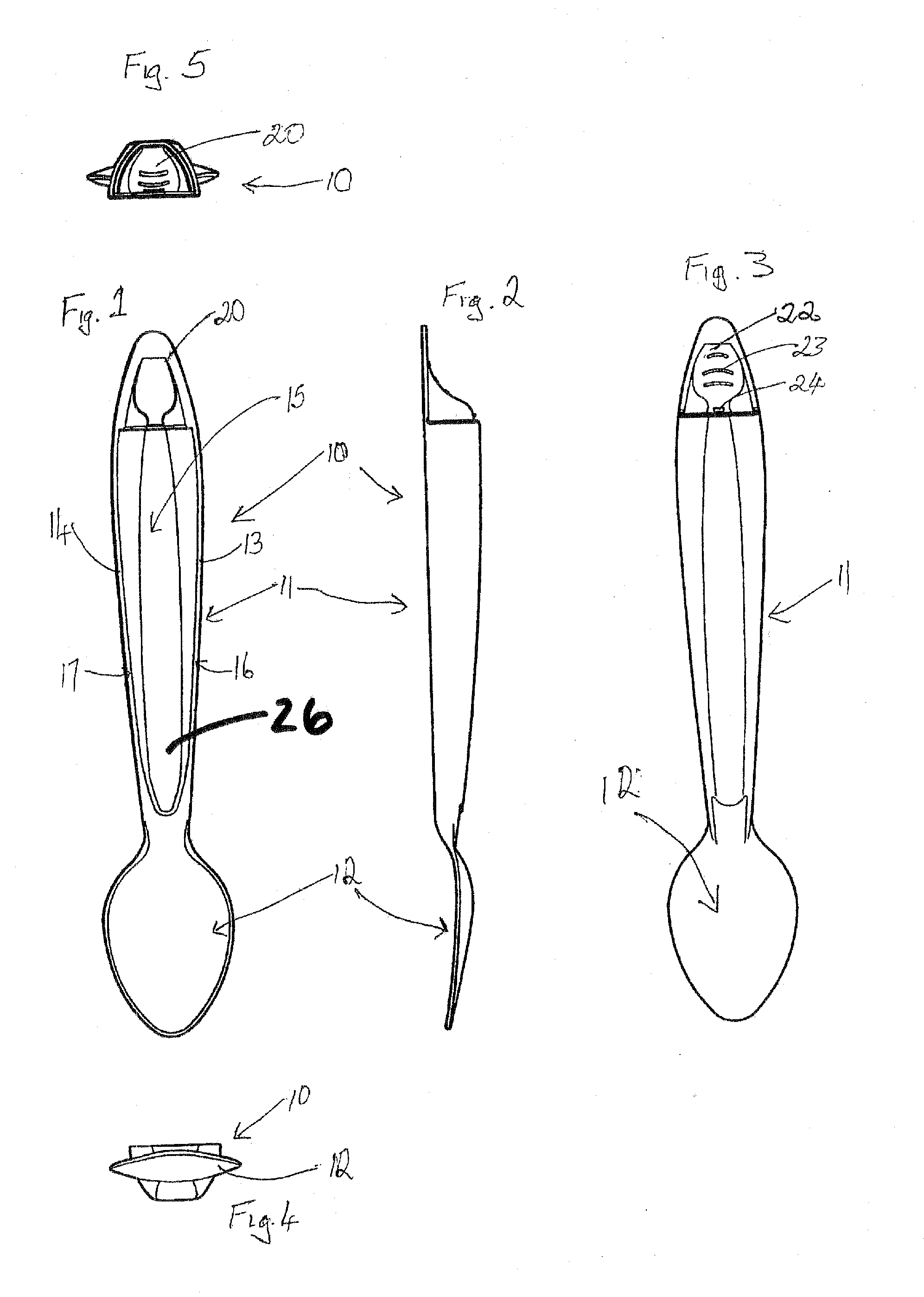
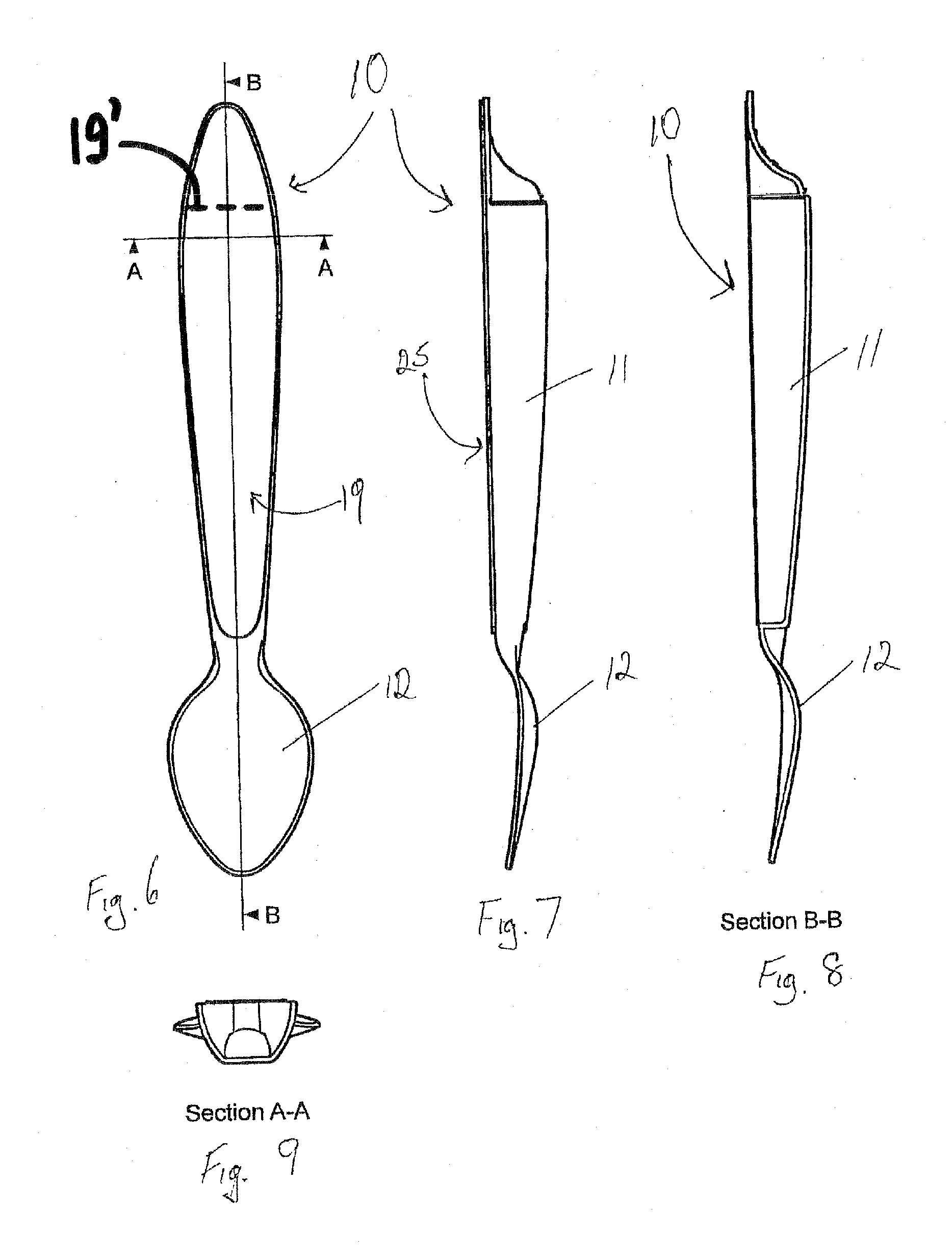
[0087] With reference to FIGS. 1 to 12, there is shown a single chamber dispensing spoon (utensil) 10 having a handle 11 integral with a spoon bowl (implement portion) 12 to form a single unit. The handle 11 has opposing side walls (first wall means) 13, 14 which form a substantially U-shaped elongate chamber (cavity) 15. The side walls 13, 14 are substantially the same height and each have a flat top surface 16, 17 respectively. As the handle 11 forms a U-shaped elongate chamber 15 to hold dispensable items (contents), it may be made of plastic material with relatively thin walls. In contrast, the surrounding walls of tubular shaped handles are comparatively thicker by design than the walls of the handle 11.

[0088] A pliable top wall (second wall means) 19 is fixable to the flat top surface 16, 17 surrounding the elongate chamber 15. The pliable top wall 19 closes chamber 15 and may be heat sealed or induction sealed where the top wall is film or foil respectively. In the present e...


PUM

PropertyMeasurementUnit
friction fitaaaaaaaaaa
areaaaaaaaaaaa
filling areaaaaaaaaaaa

Abstract

A dispensing utensil 10 comprising: a handle portion 11; an implement portion 12; a cavity 15 for storing dispensable contents, the cavity 15 defined by a first wall means 13, 14 and a second wall means 19 closing the cavity 15; characterised in that a first portion 20 of the first wall means 13, 14 is openable about a hinge formed by the second wall means 19, thereby allowing the contents to be dispensed.

Description

CROSS-REFERENCE TO RELATED APPLICATIONS [0001] This application is a continuation-in-part of International Application No. PCT / AU2004 / 001818, filed Dec. 30, 2004, the entire contents of which are hereby incorporated by reference.FIELD OF INVENTION [0002] The present invention relates to utensils that can store and dispense a liquid or solid. The present invention particularly but not exclusively is directed to dispensing spoons. Reference to dispensing spoons in the body of the specification is by way of example only and the present invention is not limited to a dispensing spoon. The term utensil within the specification includes a spoon, fork, knife, stirrer and any suitable instrument or implement. BACKGROUND OF THE INVENTION [0003] Spoons that can store and dispense ingredients have been developed to provide convenience and an alternative to the awkwardness of using separate items. The developed dispensing spoons dispense ingredients from the bowl of the spoon. The ingredients ar...

Claims


Application Information

Patent Timeline
Patent Type & Authority Applications(United States)
IPC IPC(8): B26B11/00B65D69/00A47G21/04A47J43/28A61J7/00
CPCA47G21/004A47J43/281A61J7/0015G01F19/002A61J7/0053B26B11/00A61J7/0023
Inventor TEYS, BRADLEY DONALDBEVAN, GLENNMOBBS, KEVIN JAMES
Owner SANDS INNOVATIONS
Why Eureka
Try Eureka