Fiber-reinforced composite member and method for producing structure using same

a composite member and fiber reinforcement technology, applied in the field of fiber reinforcement composite members, can solve the problems of high production cost, inability to achieve high efficiency, and inability to quickly determine the combination and position of the members to be connected

Inactive Publication Date: 2008-03-27
HONDA MOTOR CO LTD
View PDF8 Cites 38 Cited by
  • Summary
  • Abstract
  • Description
  • Claims
  • Application Information

AI Technical Summary

Benefits of technology

[0004] Accordingly, an object of the present invention is to provide a fiber-reinforced composite me

Problems solved by technology

However, the accurate positioning of members needs large assembling jigs, or optical positioning apparatuses, for instance, an apparatus of detecting the positions of other members relative to holes, etc. of one member, and moving the other members to desired positions based on the difference between the detected positions and the preset positions, resulting in high production c

Method used


Image

  • Fiber-reinforced composite member and method for producing structure using same
  • Fiber-reinforced composite member and method for producing structure using same
  • Fiber-reinforced composite member and method for producing structure using same

Examples


Embodiment Construction

[0046] [1] Fiber-Reinforced Composite Member

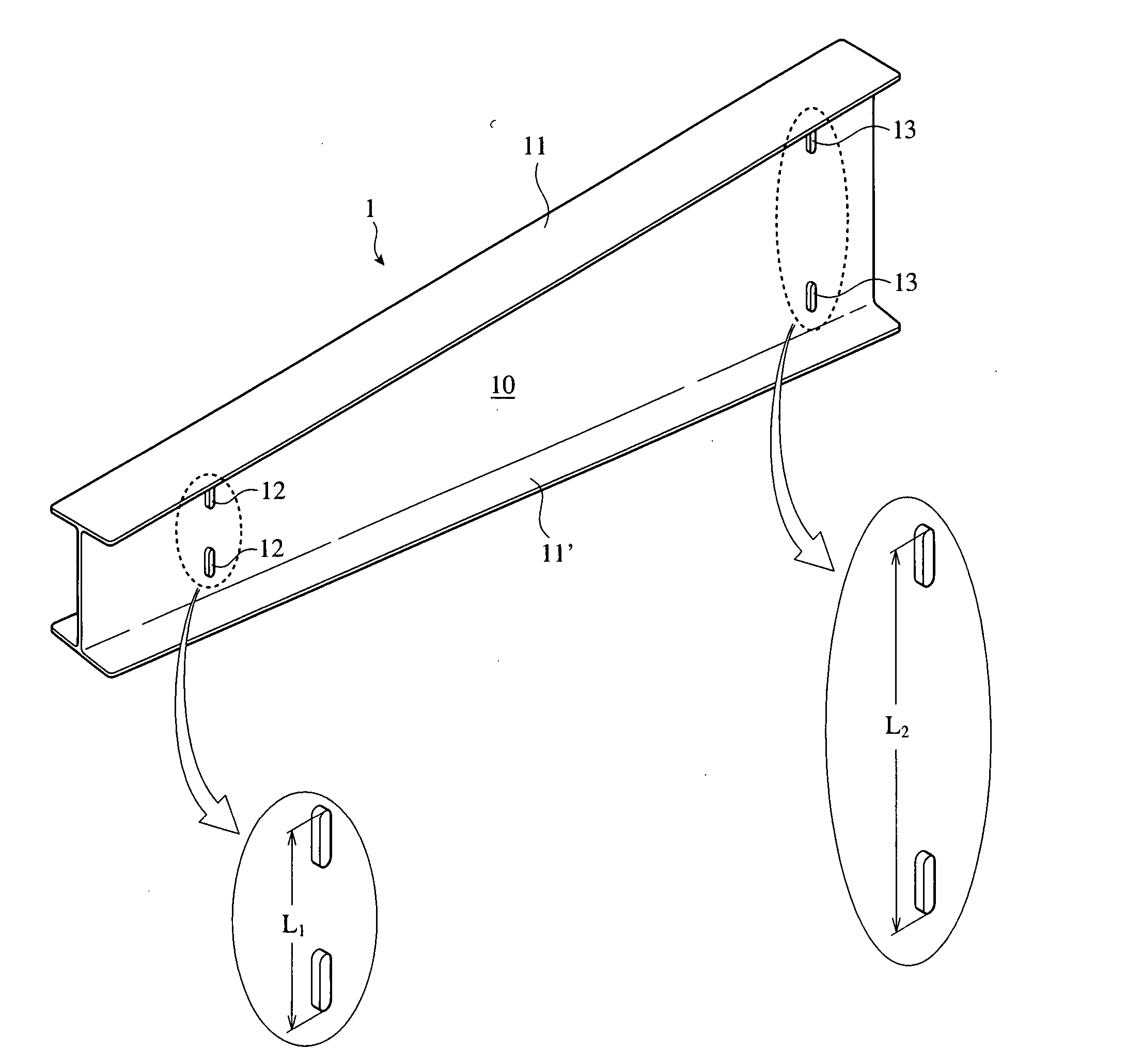
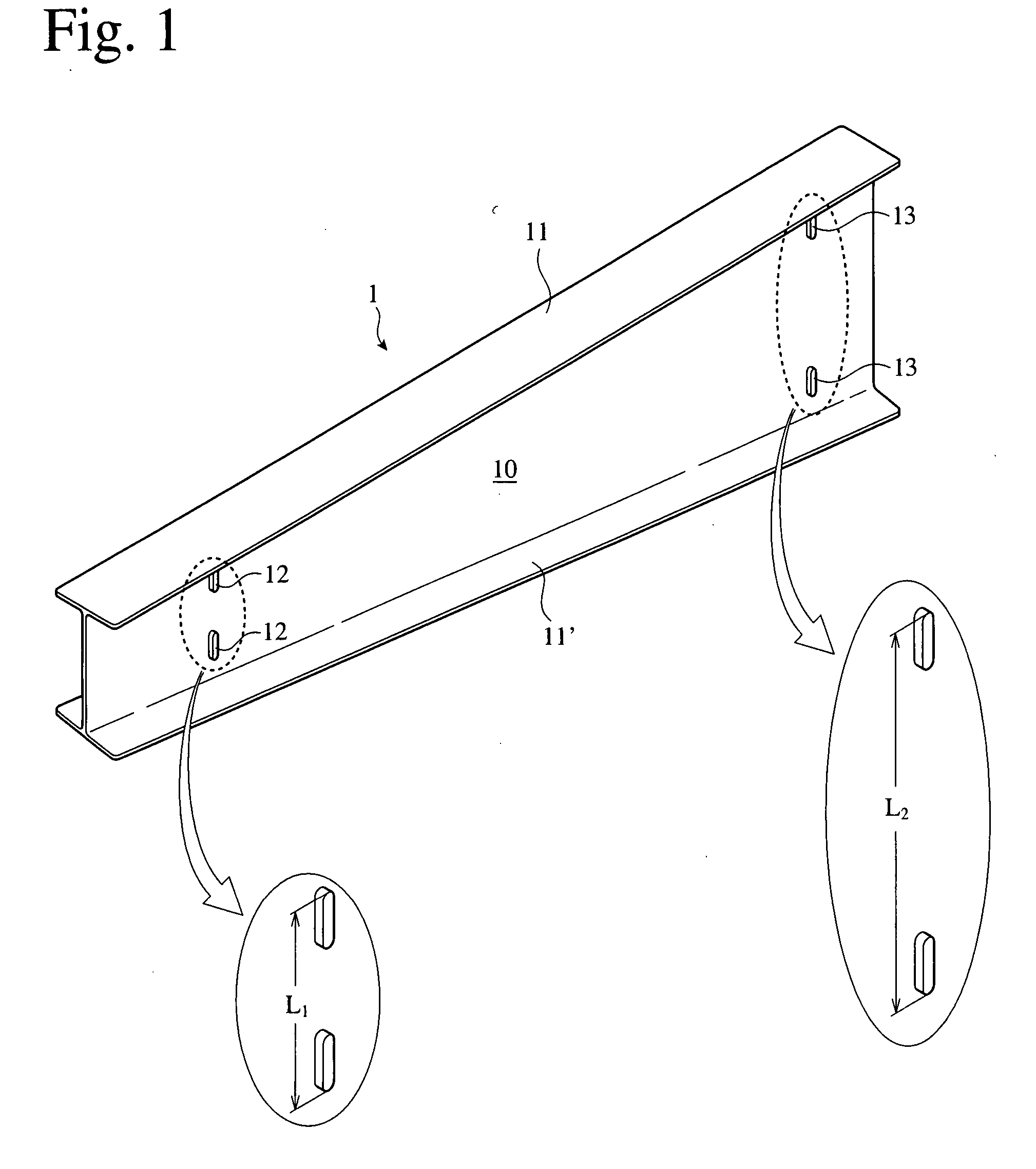
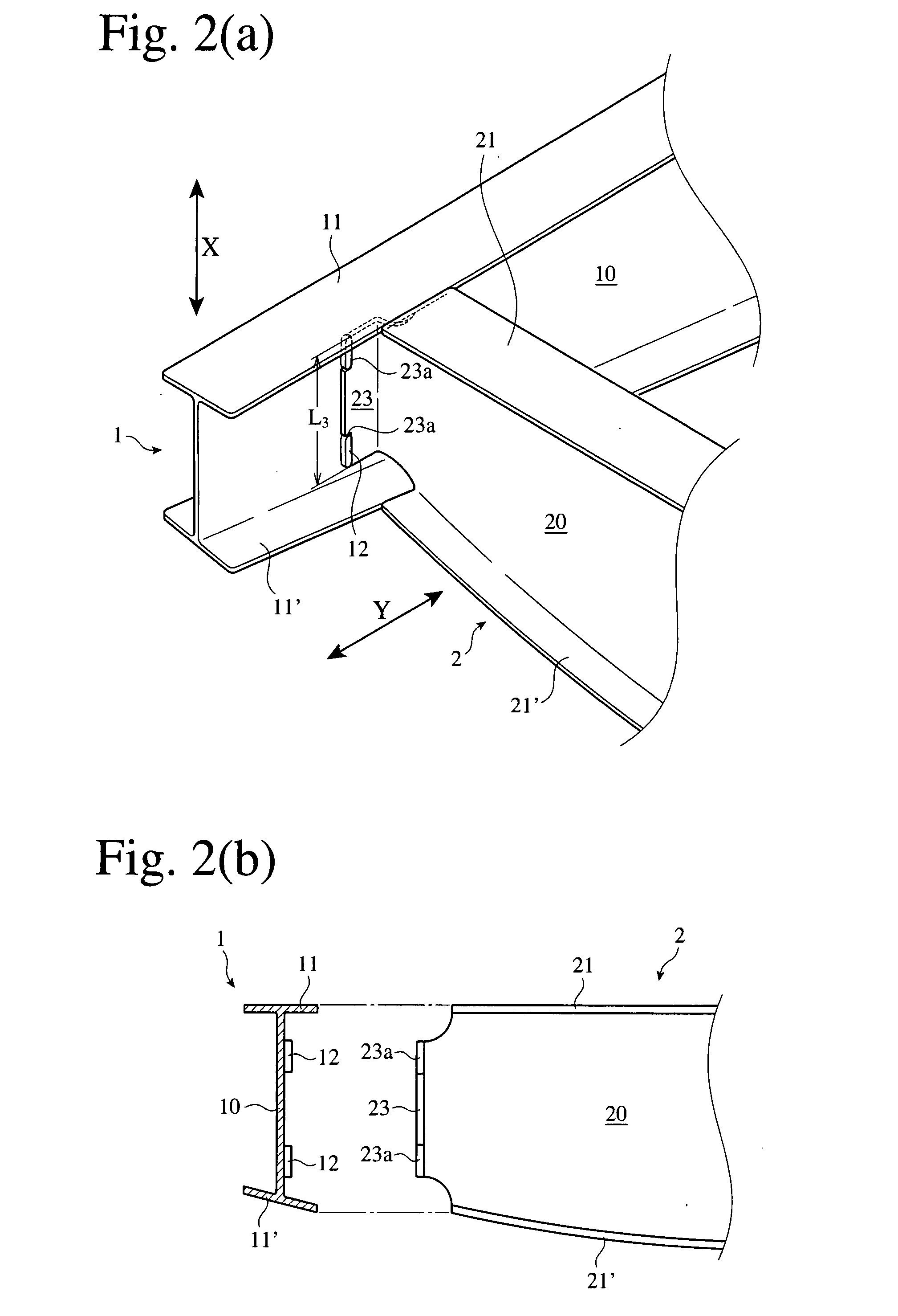
[0047]FIG. 1 shows a beam-shaped, fiber-reinforced composite member according to one embodiment of the present invention. This fiber-reinforced composite member 1, which is produced by curing prepregs of reinforcing fibers impregnated with a matrix resin, comprises a trapezoidal flat panel portion 10, flanges 11, 11′ extending from both side edges thereof toward both sides, and I-shaped, projections 12, 12, 13, 13 provided on both surfaces of the flat panel portion 10. One flange 11 vertically extends from the flat panel portion 10, while the other flange 11′ extends in a slanting direction relative to the flange 11. The projections 12 and 13 have information concerning the identification and predetermined connecting positions of said additional members to be connected to the fiber-reinforced composite member 1. In this embodiment, to identify the additional members, the distance L1 between the outer ends of the projections 12, 12 and dis...


PUM

PropertyMeasurementUnit
Sizeaaaaaaaaaa
Shapeaaaaaaaaaa

Abstract

A method for assembling a fiber-reinforced composite structure by connecting fiber-reinforced composite members to additional members, comprising the steps of providing at least one of said fiber-reinforced composite members with projections having information concerning the identification and connecting positions of said additional members, to which said fiber-reinforced composite member is to be connected, and positioning said additional members to said fiber-reinforced composite member using said projections.

Description

FIELD OF THE INVENTION [0001] The present invention relates to a fiber-reinforced composite member with which a fiber-reinforced composite structure can be produced quickly and inexpensively, and a method for assembling a fiber-reinforced composite structure using such member. BACKGROUND OF THE INVENTION [0002] When pluralities of fiber-reinforced composite members of carbon-fiber-reinforced plastics (CFRP), etc. are combined to produce such structures as fuselages and wings of aircrafts, etc., the members are conventionally disposed at the predetermined positions and connected. However, the accurate positioning of members needs large assembling jigs, or optical positioning apparatuses, for instance, an apparatus of detecting the positions of other members relative to holes, etc. of one member, and moving the other members to desired positions based on the difference between the detected positions and the preset positions, resulting in high production cost. [0003] U.S. Pat. No. 5,56...

Claims


Application Information

Patent Timeline
IPC IPC(8): E04C3/00
CPCB29C65/7802Y10T29/49826B29C66/5244B29C66/721B29C66/9672B29C70/44B29C70/54B29L2031/003B29L2031/3076B29C65/7814B29C65/00B29C66/7212B29C66/71B29C66/72141B29C65/02B29C66/1122B29C66/12841B29C66/1282B29C66/12443B29K2307/04B29K2309/08B29K2277/10B29K2075/00B29K2067/00B29K2063/00B29K2307/02B29K2061/04B29K2067/06B29K2079/00
Inventor KONDO, JUNICHIKASAHARA, YUKI
Owner HONDA MOTOR CO LTD
Why Eureka
Try Eureka