Method and system for automatically inspecting a display including a layer of liquid crystal material

a liquid crystal material and automatic inspection technology, applied in the direction of material analysis, instruments, measurement devices, etc., can solve the problems of difficult to make lcos displays, difficult to measure the thickness of something that is only one wavelength of visible light thick, localized variations of brightness and/or color in images, etc., to achieve quick and inexpensive

Inactive Publication Date: 2007-04-05
INTEGRAL VISION
View PDF10 Cites 5 Cited by
  • Summary
  • Abstract
  • Description
  • Claims
  • Application Information

AI Technical Summary

Benefits of technology

[0009] An object of the present invention is to provide a method and system for automatically inspecting a display including a layer of liquid crystal material in a quick and inexpensive fashion, without complex optics, structured light or tight mechanical tolerances to identify unacceptable variations in cell gap thickness across a viewable area of the display.

Problems solved by technology

However, when the cell gap is as thin as a single wavelength of visible light, very small differences in cell gap across the area of the display cause localized variations of brightness and / or color in the image on the display.
It is both very desirable and very difficult to make LCOS displays with a very thin cell gap which is exactly the same across the entire display.
Measuring the thickness of something that is only one wavelength of visible light thick is not easy.
However, these methods use multi-color illumination schemes and / or complex optics, and have very tight tolerances in their mechanical systems.
By their nature, the methods used to measure the exact cell gap thickness are not well suited to making measurements quickly to meet the requirements of high volume, high speed manufacturing.

Method used


Image

  • Method and system for automatically inspecting a display including a layer of liquid crystal material
  • Method and system for automatically inspecting a display including a layer of liquid crystal material
  • Method and system for automatically inspecting a display including a layer of liquid crystal material

Examples


Embodiment Construction

)

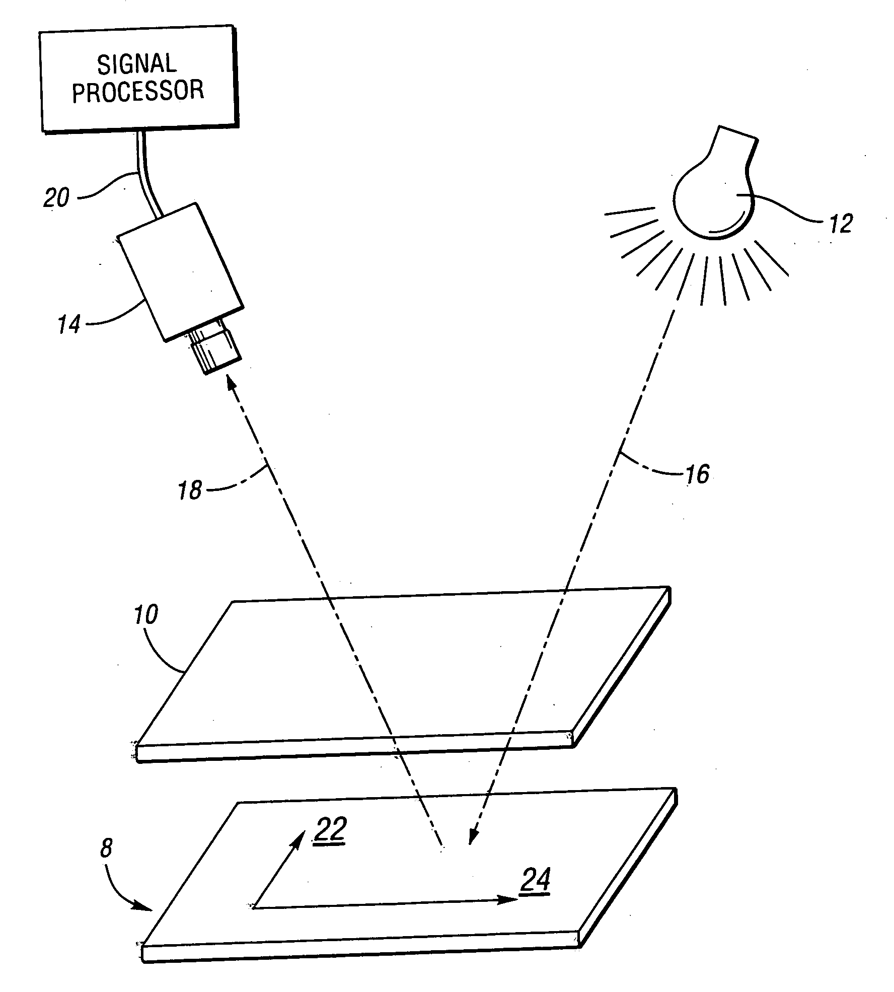
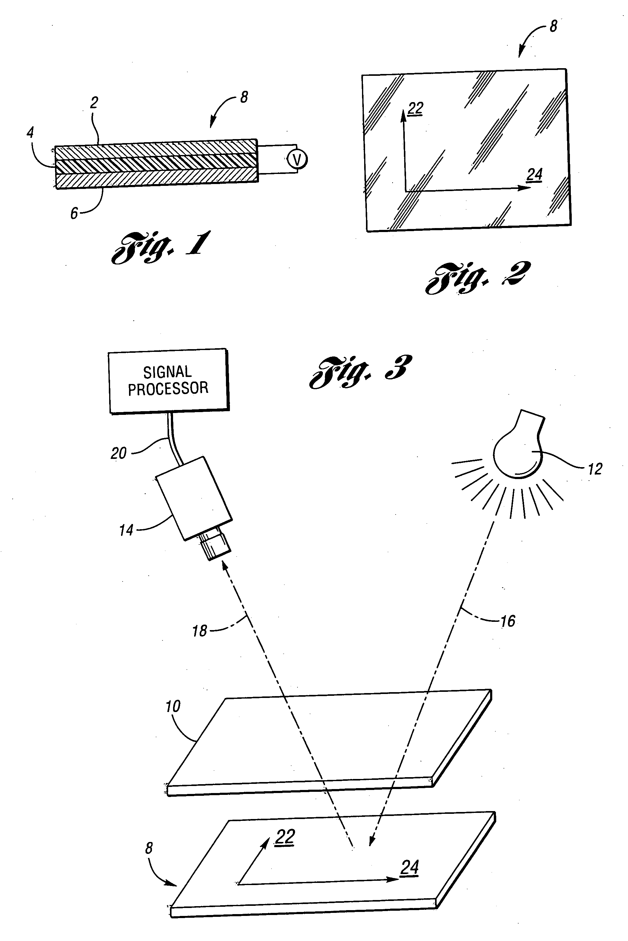
[0042] Referring now to the drawing figures, FIG. 1 illustrates the construction of a Liquid Crystal On Silicon (i.e., LCOS) display, generally indicated at 8. A layer of liquid crystal material 4 is sandwiched between a substrate of monocrystalline silicon 6 and a flat piece of glass 2.

[0043]FIG. 2 illustrates, at 22 and 24, how the major and minor axes of birefringence of the liquid crystal material 4 are oriented with respect to the edges of the LCOS display 8. Depending on the type of liquid crystal material used, these axes of birefringence may be present when the display is de-energized (no voltage applied to the pixels) or they may only appear when the display is energized with a particular voltage.

[0044]FIG. 3 shows an embodiment of a system constructed in accordance with the present invention. A linear polarization filter 10 is located in a plane parallel to the liquid crystal display 8 so that light from a light source 12, illustrated by dotted arrow 16, passes through ...


PUM

PropertyMeasurementUnit
illumination angleaaaaaaaaaa
distanceaaaaaaaaaa
thicknessaaaaaaaaaa

Abstract

A system and method are provided to rapidly inspect Liquid Crystal On Silicon (i.e., LCOS) displays to identify non-uniform cell gaps. The system includes a light source, a single polarized optical filter, and a color camera. The image acquired by the camera is analyzed to find variations in color. Excessive variations in color are used to identify excessive variations in the cell gap of the LCOS display. The arrangement of the components of the system does not require great precision and the analysis can be done very quickly.

Description

BACKGROUND OF THE INVENTION 1. Field of the Invention [0001] This invention relates to methods and systems for automatically inspecting a display including a layer of liquid crystal material. 2. Background Art [0002] A Liquid Crystal On Silicon (LCOS) display consists of a layer of liquid crystal material sandwiched between a flat substrate made of monocrystalline silicon and a flat sheet of glass. The liquid crystal material is birefringent; its major and minor axes of birefringence are always at 90 degrees to each other and are both located in the plane parallel to the surface of the glass covering the top of the LCOS display. When the LCOS display is made, the liquid crystal material is treated so that its major and minor axes of birefringence are usually oriented parallel to the top and side edges of the generally rectangular LCOS display. [0003] The silicon substrate is actually an integrated circuit containing transistors, resistors and other circuitry together with metallized...

Claims


Application Information

Patent Timeline
Patent Type & Authority Applications(United States)
IPC IPC(8): G01N21/86
CPCG01N21/23G01N2021/845G01N2021/8477
Inventor MICHNIEWICZ, MARK A.BLOWERS, ANDREW
Owner INTEGRAL VISION
Why Eureka
Try Eureka