
Device and method for seal verification by penetrant inspection of a nuclear fuel assembly

a technology of seal verification and nuclear fuel, which is applied in the direction of nuclear elements, climate sustainability, greenhouse gas reduction, etc., can solve the problems of reducing the efficiency of nuclear fuel assembly seal verification, affecting the integrity of nuclear fuel rods, and not being able to determine which nuclear fuel, so as to reduce or even eliminate the additional handling operations and limit the interference effects

Active Publication Date: 2019-11-28
FRAMATOME ANP
View PDF0 Cites 7 Cited by
  • Summary
  • Abstract
  • Description
  • Claims
  • Application Information

AI Technical Summary

Benefits of technology

The present invention provides a device for testing leaks in nuclear fuel assemblies by sipping on them. The device includes a collection assembly that prevents water from escaping and collects products that may contain fission products released by the fuel assembly. The device is simple, fast, inexpensive, and reduces the handling of the fuel assemblies while minimizing interference from adjacent assemblies.

Problems solved by technology

During its utilization in a nuclear reactor, a nuclear fuel rod of a nuclear fuel assembly can lose its integrity and have a leakage for example by piercing or cracking of the cladding of the rod.
However, these measurements do not make it possible to determine which nuclear fuel assembly contains a fuel rod having a leakage.
However, leakage testing by in-core sipping on a nuclear fuel assembly can be disrupted or interfered with by the presence of potential fission products trapped in the coolant and / or coming from adjacent assemblies.
Furthermore, this leakage testing is only made possible for nuclear fuel assemblies including a housing surrounding the bundle of nuclear fuel rods and acting as sipping cell, as is the case for the nuclear fuel rods of boiling water reactors (BWR).
Thus, such sipping devices have only a very limited effectiveness for nuclear fuel assemblies not including a housing, in particular nuclear fuel assemblies for pressurized water reactors (PWR).
Indeed, due to its unloading, the nuclear fuel assembly is generally raised to a depth lower than that of the nuclear reactor, such that the pressure outside the nuclear fuel assembly decreases, which causes a release of fission products outside a nuclear fuel rod having a leakage.
However, in some cases, in particular when the sipping apparatus is contaminated by fission products released by a previously verified nuclear fuel assembly, this loading machine does not make it possible to determine with certainty whether a nuclear fuel assembly has a leakage, and the nuclear fuel assembly can only be classified as “doubtful”.
However, in the old nuclear power plants, these sipping cells are also old, and their maintenance and update are costly.
However, such sipping cells are generally cumbersome, heavy, and time-consuming to install, decontaminate and uninstall.
This therefore requires many handling operations of the nuclear fuel assemblies, which are time-consuming to perform and increase the risk of damaging a nuclear fuel assembly.
Such sipping cells represent a costly investment with respect to their episodic use.

Method used


Image

  • Device and method for seal verification by penetrant inspection of a nuclear fuel assembly
  • Device and method for seal verification by penetrant inspection of a nuclear fuel assembly
  • Device and method for seal verification by penetrant inspection of a nuclear fuel assembly

Examples


Embodiment Construction

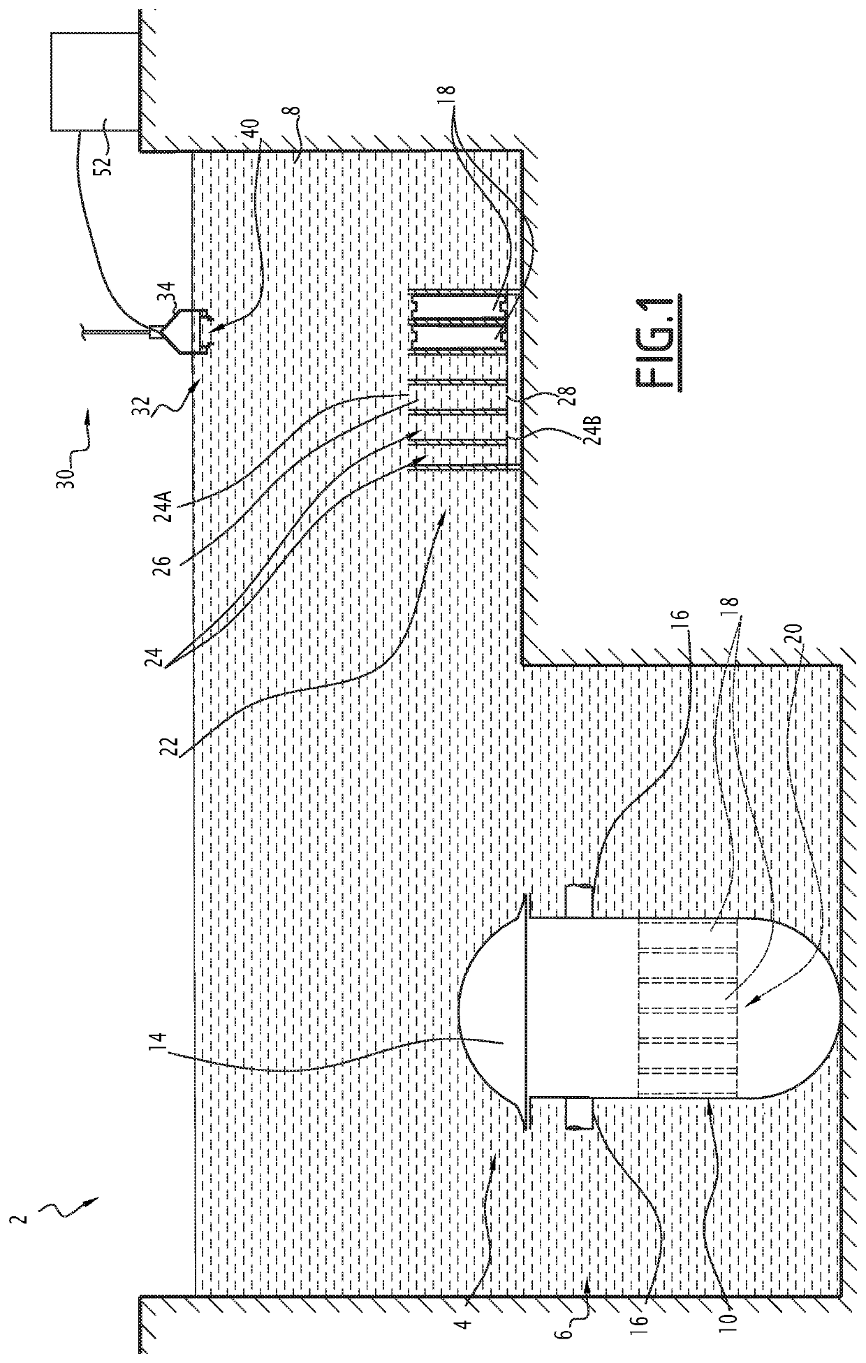
[0046]The nuclear power plant 2 illustrated in FIG. 1 comprises a nuclear reactor 4 arranged in a reactor well 6, and a storage pool 8 for storing nuclear fuel assemblies 18 discharged from a nuclear reactor 4. The storage pool 8 is in communication with the reactor well 6.

[0047]The reactor well 6 and the storage pool 8 are filled with water to provide radiological protection for the assembly. The water level is provided so that the handling necessary during maintenance operations, and in particular the handling of the nuclear fuel assemblies 18, are done underwater.

[0048]The nuclear reactor 4 comprises a vessel 10 and a cover 14 mounted removably on the vessel 10. The vessel 10 is connected to a primary circuit by tubings 16 for the circulation of a coolant through the vessel 10.

[0049]The nuclear reactor 4 is loaded with a set of nuclear fuel assemblies 18 arranged side by side and together forming the core 20 of the nuclear reactor 4. For the loading and unloading of the nuclear f...


PUM


Abstract

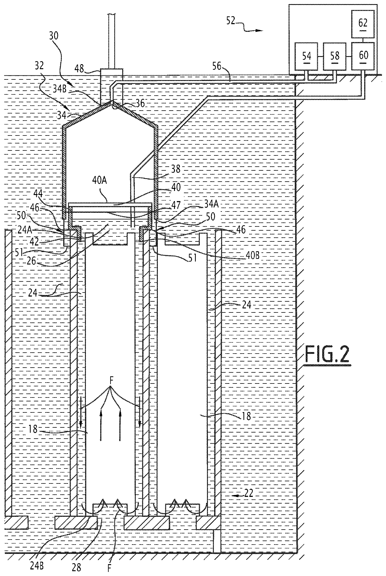
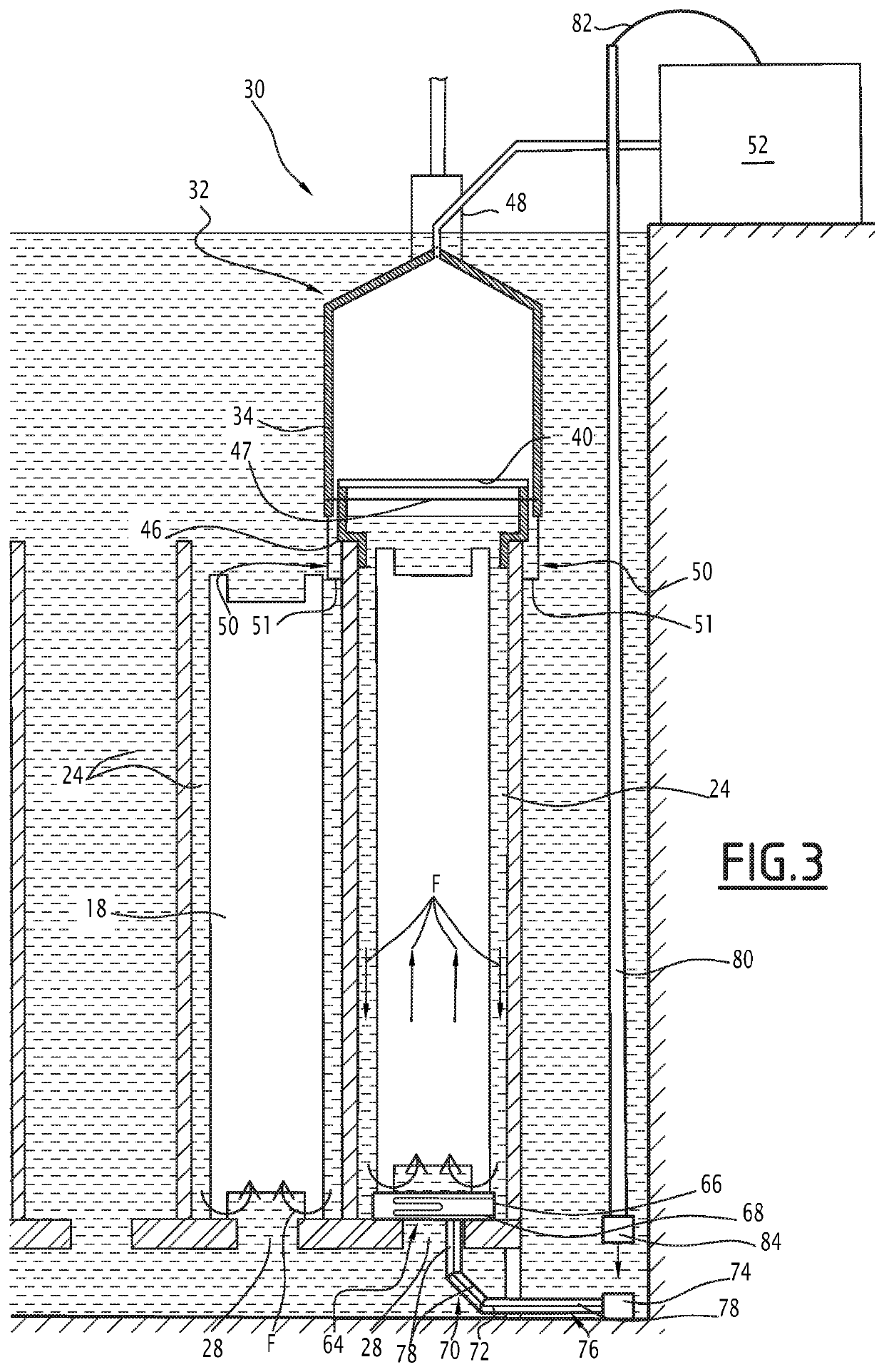
A leakage testing device for testing leakage of a nuclear fuel assembly (18) by sipping, includes a collection assembly (32) that is configured to close an upper end (24A) of a cell (24) of a storage rack (22) for storing nuclear fuel assembly / ies (18) discharged from a nuclear reactor (4), so as to prevent water contained in the cell (24) from escaping via the upper end (24A) of the cell (24), and to collect products containing possible fission products released by a nuclear fuel assembly (18) contained in the cell (24).

Description

[0001]The present invention relates to a device and a method for leakage testing by sipping of a nuclear fuel assembly.[0002]A nuclear fuel reactor comprises a vessel in which a plurality of nuclear fuel assemblies are arranged together forming the core of the nuclear reactor. The vessel has a removable cover that must be removed to load and unload the nuclear fuel assemblies.BACKGROUND[0003]The nuclear reactor is generally arranged in a reactor well filled with water when the reactor is stopped, the well communicating with at least one pool that is also filled with water, making it possible to perform the maintenance operations.[0004]Each nuclear fuel assembly contains nuclear fuel. More specifically, each nuclear fuel assembly comprises a bundle of nuclear fuel rods, each nuclear fuel rod comprising an elongate tubular cladding closed at both of its ends and containing nuclear fuel.[0005]During operation, a coolant circulates through the core, along the nuclear fuel assemblies, an...

Claims


Application Information

Patent Timeline
Patent Type & Authority Applications(United States)
IPC IPC(8): G21C17/07
CPCG21C17/07G21C19/07Y02E30/30
Inventor COUSTOURIER, FRANCKROILLET, SERGE
Owner FRAMATOME ANP
Learn More