
Locating and drilling determinate assembly holes using a coordinate measuring device

a technology of coordinate measuring device and assembly hole, which is applied in the direction of mechanical measuring arrangement, manufacturing tools, instruments, etc., can solve the problems of reducing the efficiency and affecting the accuracy of the assembly stage, so as to reduce the waste of time, tooling and cost, and the effect of locating and drilling da holes quickly and inexpensively

Active Publication Date: 2009-11-10
THE BOEING CO
View PDF16 Cites 7 Cited by
  • Summary
  • Abstract
  • Description
  • Claims
  • Application Information

AI Technical Summary

Benefits of technology

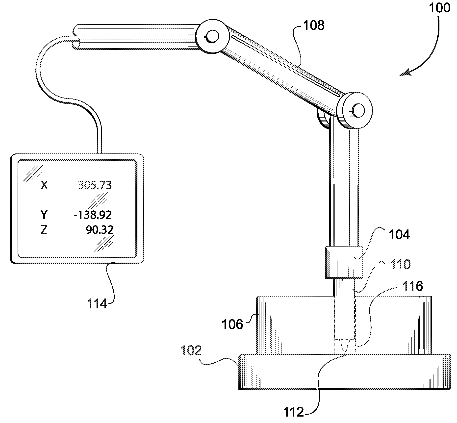
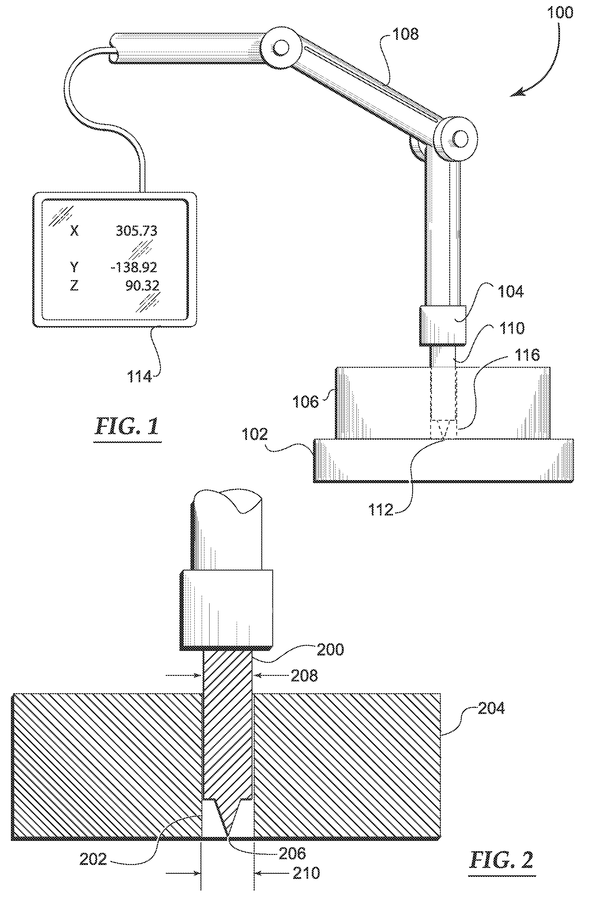
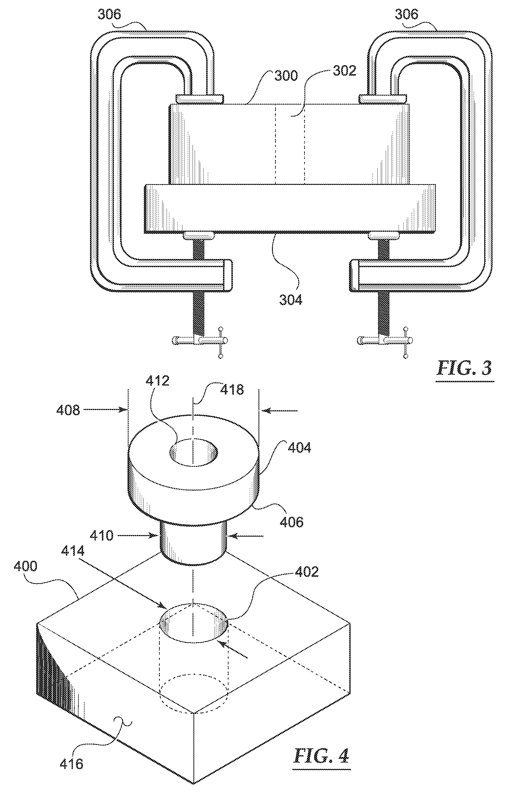
The patent describes a system and methods for quickly and accurately locating and drilling holes in existing parts without the need for complicated tooling. This system uses a coordinate measuring device (CMD) and a guide element with a reference hole to position the CMD probe tip at a target position on the part. A drill bushing with a drill bit guide hole is then inserted into the guide element's reference hole, and the drill bit guide hole is used to guide the drill bit to create the hole. This system is efficient, cost-effective, and repeatable, allowing for the benefits of drilling holes to be realized without waste. The invention is in line with the principles of lean manufacturing and can be easily integrated into existing manufacturing processes.

Problems solved by technology

The tooling has been used to accurately locate the features, but is often complicated and costly, as well as part-specific.
For these reasons, a substantial amount of the cost savings to be gained by DA in the assembly stages can be lost up front in creating the alignment features.

Method used


Image

  • Locating and drilling determinate assembly holes using a coordinate measuring device
  • Locating and drilling determinate assembly holes using a coordinate measuring device
  • Locating and drilling determinate assembly holes using a coordinate measuring device

Examples


Embodiment Construction

[0020]The following detailed description is merely illustrative in nature and is not intended to limit the embodiments of the invention or the application and uses of such embodiments. Furthermore, there is no intention to be bound by any expressed or implied theory presented in the preceding technical field, background, brief summary or the following detailed description.

[0021]The following description may refer to elements or features being “connected” or “coupled” together. As used herein, unless expressly stated otherwise, “connected” means that one element / feature is directly joined to (or directly communicates with) another element / feature, and not necessarily mechanically. Likewise, unless expressly stated otherwise, “coupled” means that one element / feature is directly or indirectly joined to (or directly or indirectly communicates with) another element / feature, and not necessarily mechanically. Thus, although the schematic shown in FIG. 1 depicts one example arrangement of e...


PUM

PropertyMeasurementUnit
diameteraaaaaaaaaa
DAaaaaaaaaaa
outer diameteraaaaaaaaaa

Abstract

A system and methods for locating and drilling determinate assembly (DA) holes using a coordinate measuring device (CMD) are disclosed. A system includes a CMD having a probe tip, a guide element having a reference hole for receiving the probe tip, and a drill bushing having a drill bit guide hole for accurately drilling a DA hole at a target position. Methods for locating and drilling DA holes comprise steps of: calibrating a CMD; inserting a CMD probe into a reference hole of a guide element; positioning the CMD probe and guide element at a target position on a part; maintaining the guide element at the target position; removing the CMD probe from the guide element; inserting a drill bushing into the reference hole of the guide element; and drilling a DA hole in the part, utilizing a drill bit guide hole located in the drill bushing.

Description

TECHNICAL FIELD[0001]Embodiments of the present invention relate generally to determinate assembly (DA) techniques for indexing assemblies relative to each other. More particularly, embodiments of the present invention relate to a system and method for locating and drilling DA holes using a coordinate measuring device (CMD).BACKGROUND[0002]DA is a technique used in manufacturing and assembly environments whereby key alignment features such as holes are used to index parts and assemblies relative to each other. DA holes can be precisely positioned and sized for use as fastener locations. DA holes can also be used to locate parts and assemblies in a manner that minimizes variation through the use of geometric dimensioning and tolerancing. DA is especially useful for assembling large parts or assemblies together. One benefit of DA is that it can eliminate the need for certain assembly tooling and thereby reduce design and manufacturing costs. Accordingly, DA manufacturing techniques ar...

Claims


Application Information

Patent Timeline
Patent Type & Authority Patents(United States)
IPC IPC(8): B23B49/00B23B35/00
CPCB23B35/00B23B47/287Y10T408/03B23B2260/128B23B2260/026
Inventor KILWIN, JEFFREY J.STECKEL, RICHARD J.HARMON, JERRY R.
Owner THE BOEING CO
Learn More