Dosage-dispensing device for powders or pastes

Active Publication Date: 2008-03-27
METTLER TOLEDO GMBH
View PDF9 Cites 15 Cited by
  • Summary
  • Abstract
  • Description
  • Claims
  • Application Information

AI Technical Summary

Benefits of technology

[0007]In view of the limitations in using the dosage-dispensing device of the foregoing description, the present disclosure therefore

Problems solved by technology

In view of the requirements that are placed on the attachment of the source container in the dosage-dispensing device, the arrangement of the foregoing description has the disadvantage that the source container and the mechanical interface connections of the dosage-dispensing device to the source container have to be matched to each other very precisely in order to allow the drive shaft to be coupled to the drive mechanism when the source container is set into the dosage-dispensing device.
The tight tolerances on fit and position associated with this requirement make the parts very expensive to produce.
Furthermore, depending on the design of the connecting flange, setting the source container into place is a time-consuming operation due to the required alignment operations.
It is not impossible to store small substance quantities in l

Method used


Image

  • Dosage-dispensing device for powders or pastes
  • Dosage-dispensing device for powders or pastes
  • Dosage-dispensing device for powders or pastes

Examples


Embodiment Construction

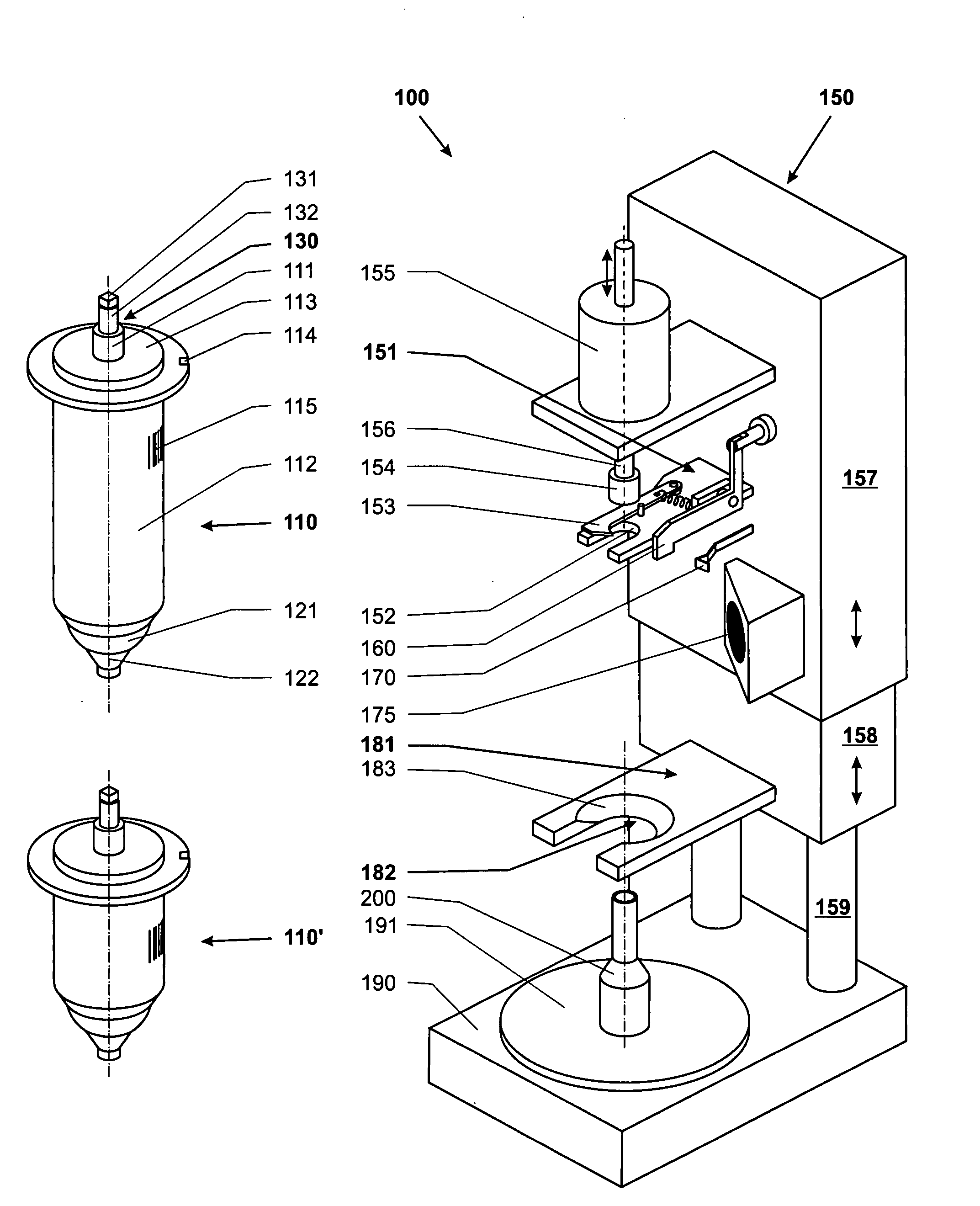
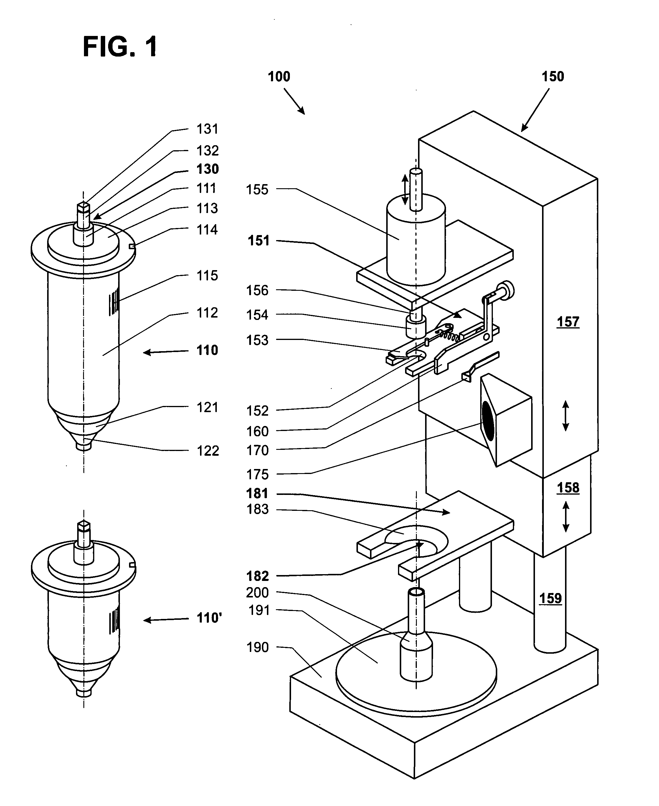
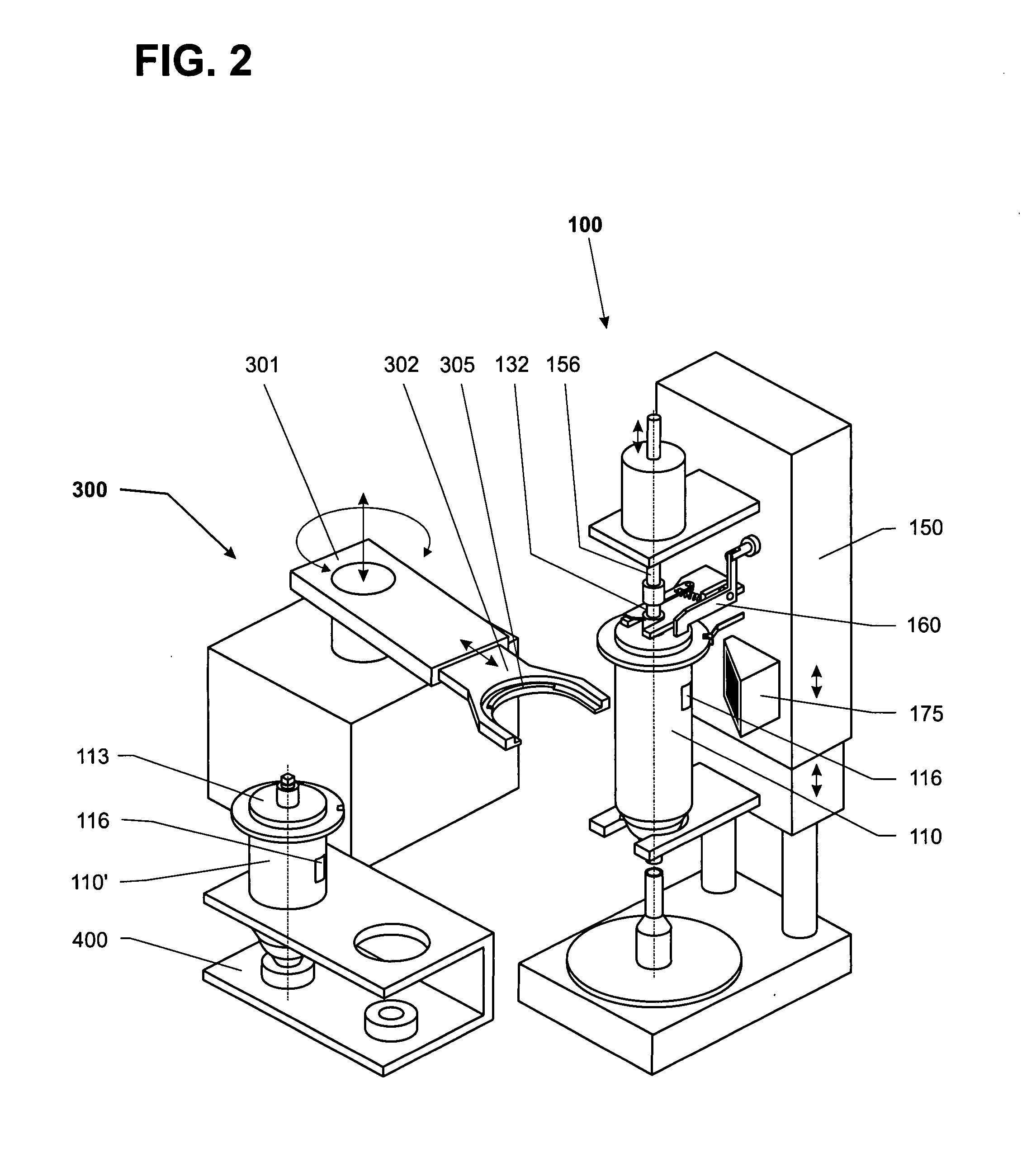
[0040]FIG. 1 shows a dosage-dispensing device 100 with a drive device 150 and a source container 110 that can be set into and removed from the drive device. The drive device 150 includes a top part 157 and a bottom part 158 which are capable of linear movement substantially in the direction of the load towards each other and away from each other. This makes it possible to use source containers 110, 110′ of different length. To ensure a simple exchange of the source container 110 and a safe and accurate dosage-dispensing operation, the source container 110 and the drive device 150 need to be equipped with suitable mechanical, possibly mechanical and electrical, connector elements of matching configuration for a form-fitting mutual engagement. The source container 110 includes at least one form element 111 which is held in a defined position in a plane that extends orthogonal to the load direction by a first counterpart element 151 which is formed on or connected to the top part 157. ...


PUM

PropertyMeasurementUnit
Volumeaaaaaaaaaa
Shapeaaaaaaaaaa
Widthaaaaaaaaaa

Abstract

A dosage-dispensing device for substances in powder- or paste form includes a drive device and a source container that can be set into the drive device, wherein a dosage-dispensing head with a closure body that can be set into rotation by a drive mechanism and is connected to a closure shaft which is movably constrained in the source container is arranged at the underside of the source container when the latter is in its operating position. The closure shaft has a coupler part in a passage area where it passes through the topside of the source container. The coupler part is configured to be coupled to and uncoupled from a drive shaft of the drive device. The source container has a first form element which is designed for form-fitting engagement with a first counterpart element formed on the drive device and serves to precisely position the coupler part in relation to the drive shaft in a plane that is orthogonal to the axis of rotation of the drive shaft. The source container further has a second form element which is designed for form-fitting engagement with a second counterpart element formed on the drive device (150) and which, when in operating position, serves to precisely position the dosage-dispensing head in relation to a target container which is arranged below the dosage-dispensing head.

Description

RELATED APPLICATIONS[0001]This application claims priority under 35 U.S.C. §119 to EP Application 06121165.2 filed in Europe on Sep. 25, 2006, the entire contents of which are hereby incorporated by reference in their entireties.TECHNICAL FIELD[0002]The present disclosure relates to a device for dispensing measured doses of substances in powder- or paste form.BACKGROUND INFORMATION[0003]Dosage-dispensing devices of this kind find application in particular in dispensing small quantities, for example of toxic substances, with high precision into small target containers. Frequently, such recipient containers are placed on a balance in order to weigh the substance delivered out of the dosage-dispensing device, so that the substance can subsequently be further processed according to given specifications.[0004]The substance to be dispensed is contained for example in a source container which is equipped with a dispensing head. It is desirable to deliver the substance to the outside throug...

Claims


Application Information

Patent Timeline
IPC IPC(8): B65B3/04
CPCG01F13/001B65B3/30
Inventor LUCHINGER, PAULEHRBAR, SANDRA
Owner METTLER TOLEDO GMBH
Why Eureka
Try Eureka