Child car seat portable fan assembly

a fan assembly and car seat technology, applied in the field of child car seat fan assembly, can solve the problems of child being substantially blocked from any direct air flow, stagnant air in the back of the care, and undesirable for a child, so as to prevent injury to an item, increase the aesthetic appeal of the assembly, and prevent child injury.

Inactive Publication Date: 2008-03-27
HAGLER GRAY TERRIE +1
View PDF23 Cites 12 Cited by
  • Summary
  • Abstract
  • Description
  • Claims
  • Application Information

AI Technical Summary

Benefits of technology

[0014]According to yet another preferred embodiment of the invention, the portable fan assembly adapted for seatmant on a vehicular surface in a spaced apart relationship with a child safety seat, comprising a front portion, a back portion, two side portions, a top portion, and a bottom portion. An interior void is positioned centrally within the assembly, extending from the front portion to the back portion. A fan unit having a housing is positioned within the interior void, and the fan housing includes a central hub and at least a pair of fan blades mounted to the hub. The central hub is rotationally connected by an elongated shaft to a fan motor that is configured to be operative and to rotate the fan blades for directing air through the interior void. The front portion, back portion, two side portions, the top portion, and the bottom portion are substantially padded for providing a cushioning effect that prevents injury to a child situated in close proximity to the assembly. A protective grill is located about the housing for prohibiting the intrusion of items into the fan blades, such as a child's fingers. At least one attachment strap is configured to securely position the assembly to a vehicular seat; and a decorative design is incorporated into the front portion of the assembly for increasing the aesthetic appeal of the assembly.
[0015]According to yet another preferred embodiment of the invention, th

Problems solved by technology

As a result, the child is substantially blocked from any direct air flow supplied by the vehicle's ventilation system by the seat backs of the front seats.
In ot

Method used


Image

  • Child car seat portable fan assembly
  • Child car seat portable fan assembly
  • Child car seat portable fan assembly

Examples


Embodiment Construction

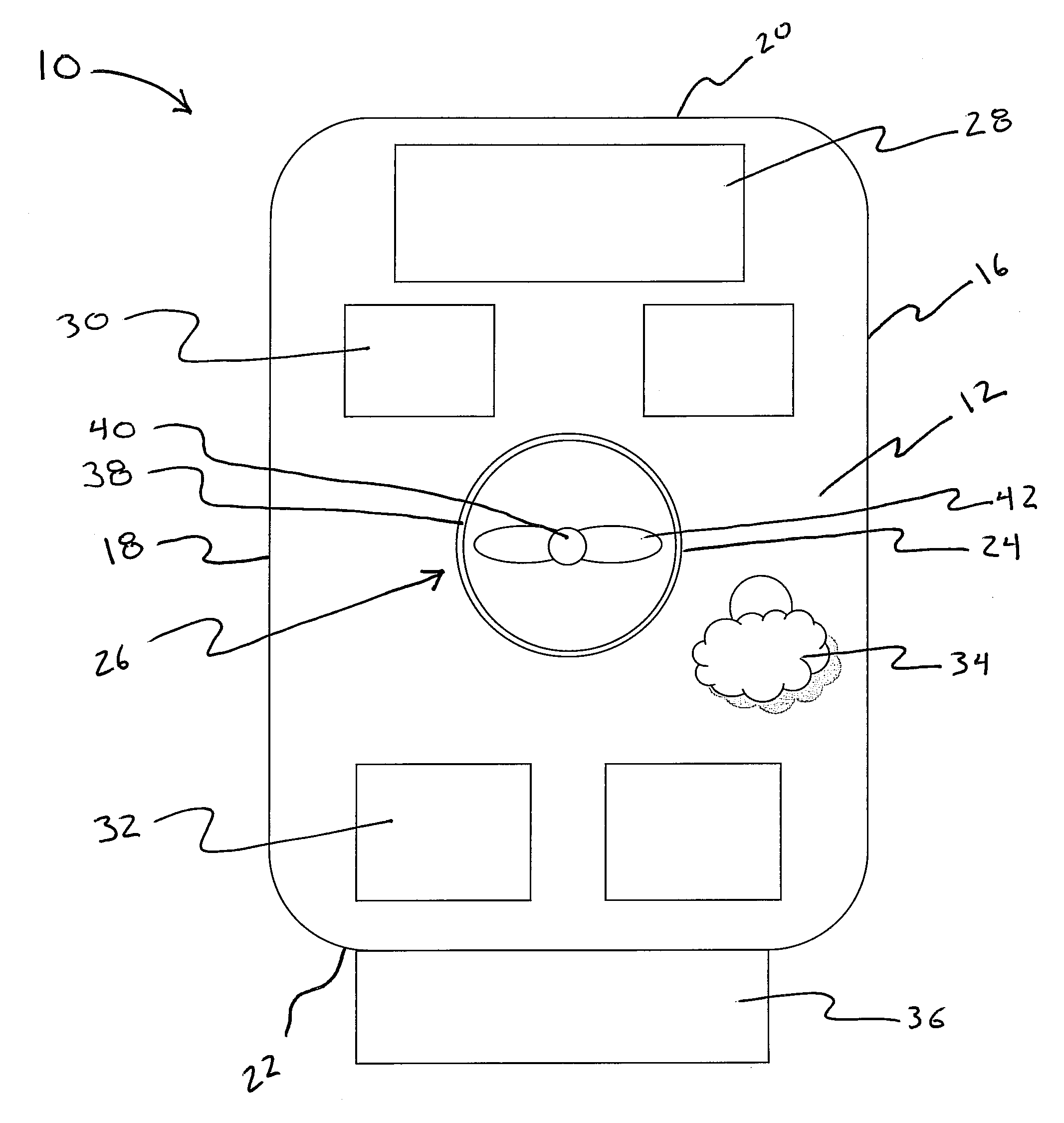
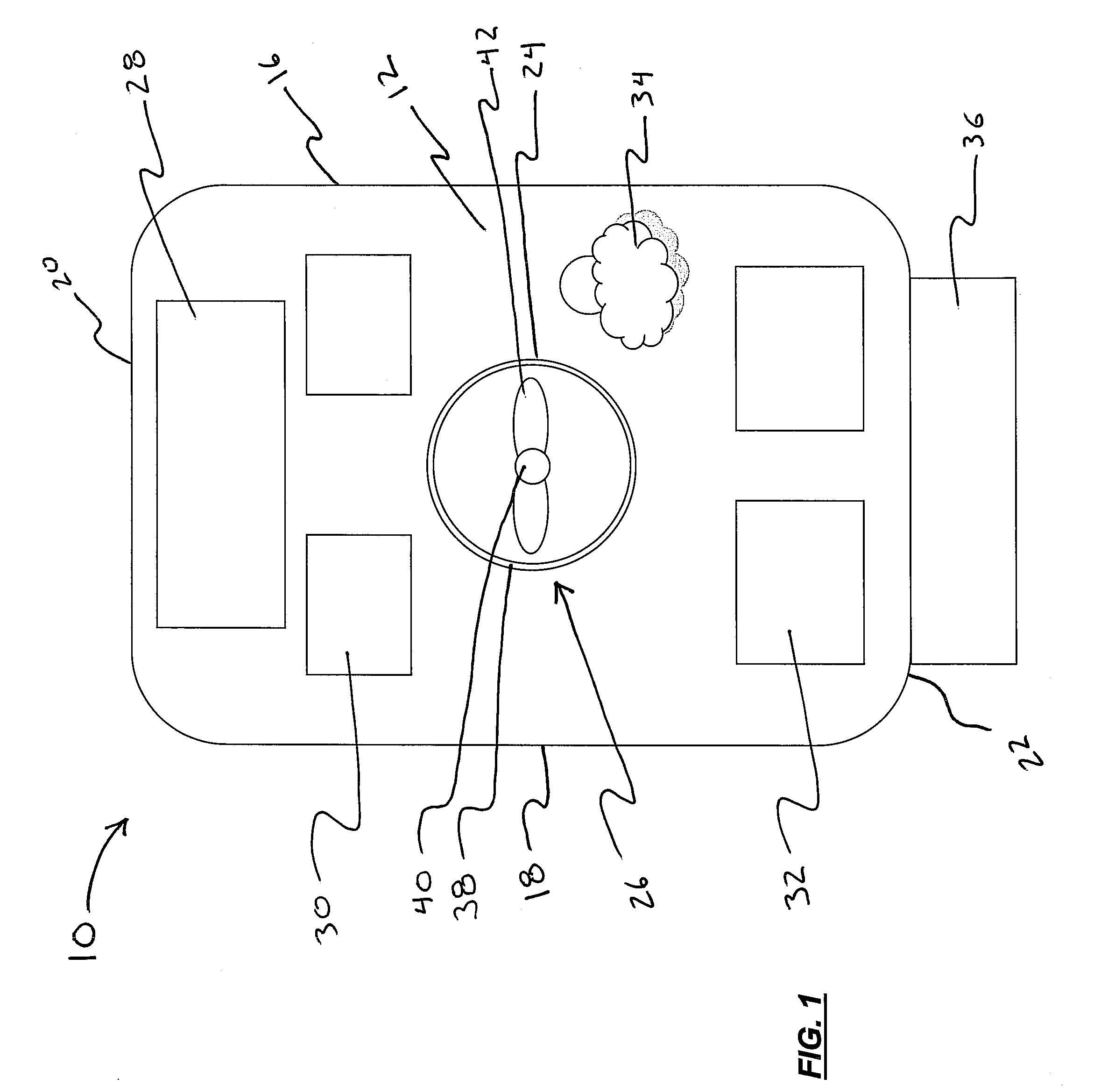
[0020]Referring now specifically to the drawings, an exemplary portable fan assembly is illustrated in FIG. 1 and is shown generally at reference numeral 10. As illustrated, the assembly 10 has a front portion 12, a back portion 14 (as illustrated in FIG. 3), two side portions 16 and 18, a top portion 20, and a bottom portion 22. An interior void 24 is centrally located within the front portion 12 that houses a fan unit 26. The fan unit 26 preferably has a low profile which is substantially flush with the top portion 20 and back portion 22 of the assembly 10 and extending into the interior void 24.

[0021]Optionally, the front portion 12 of the assembly 10 may include a reflective surface 28, such as a mirror, that is fixedly attached to the uppermost area of the front portion 12 of the assembly 10. The purpose of the reflective surface 28 is to allow the operator of a motor vehicle to clearly view the child sitting in front of the assembly 10. Preferably, the reflective surface 28 is...


PUM


Abstract

A portable fan assembly adapted for seatmant on a vehicular surface in a spaced apart relationship to a child car seat, comprising a front portion, a back portion, two side portions, a top portion, and a bottom portion. An interior void is positioned centrally within the assembly, extending from the front portion to the back portion. A fan unit having a housing that is positioned within the interior void. The housing includes a central hub and at least a pair of fan blades that are mounted to the hub. The hub is rotationally connected by an elongated shaft to a fan motor configured to be operative for rotating the fan blades for directing air through the interior void. The front portion, back portion, two side portions, the top portion, and the bottom portion are substantially padded for providing a cushioning effect that prevents injury to an child situated in close proximity to the assembly, and at least one attachment strap configured to securely position the assembly to a vehicular seat.

Description

CROSS-REFERENCE TO RELATED APPLICATION[0001]The present non-provisional patent application claims the benefit of U.S. Provisional Patent Application No. 60 / 846,239 entitled “INFANT CAR SEAT FAN ASSEMBLY,” filed Sep. 21, 2006, which is herein incorporated in full by reference.FIELD OF THE INVENTION[0002]The present invention relates generally to a child car seat fan assembly, and more particularly to a portable fan assembly to be used in conjunction with a child car seat that is safe and suitable to be utilized in close proximity to a child.BACKGROUND OF THE INVENTION[0003]When a child under a certain age, as determined by law, travels in a motor vehicle, the child is required to be securely fastened within a child safety seat to prevent injury in the unfortunate, but occasional, vehicle accident. Child safety seats are designed, and in most instances required by law, to be positioned within the back seat of a motor vehicle. As a result, the child is substantially blocked from any di...

Claims


Application Information

Patent Timeline
IPC IPC(8): A47C7/72
CPCB60H1/00264F24F7/007F04D25/084F04D25/08
Inventor HAGLER-GRAY, TERRIEGRAY, LEE
Owner HAGLER GRAY TERRIE
Why Eureka
Try Eureka