Combining outputs of different light sources

a technology of outputs and light sources, applied in the field of blending light, can solve the problems of inefficiency of green leds, inefficiency of current available red and blue leds, and limitations of embodiment,

Inactive Publication Date: 2008-03-27
LIGHT PRESCRIPTIONS INNOVATORS
View PDF9 Cites 113 Cited by
  • Summary
  • Abstract
  • Description
  • Claims
  • Application Information

AI Technical Summary

Problems solved by technology

An important problem that needs to be addressed is how to combine the output from multiple LEDs sources to produce a high-flux, high-luminance source, wherein the “combined source” has a smaller étendue than the combined values of the individual LED sources.
This embodiment, however, as well as others in that application, has limitations.
First, the device in FIG. 1 can only mix one green, one blue and one red LED a...

Method used


Image

  • Combining outputs of different light sources
  • Combining outputs of different light sources
  • Combining outputs of different light sources

Examples


Embodiment Construction

[0036] Reference will now be made in detail to embodiments of the present invention, example of which is illustrated in the accompanying drawings, in which like numbers represent the same or similar elements.

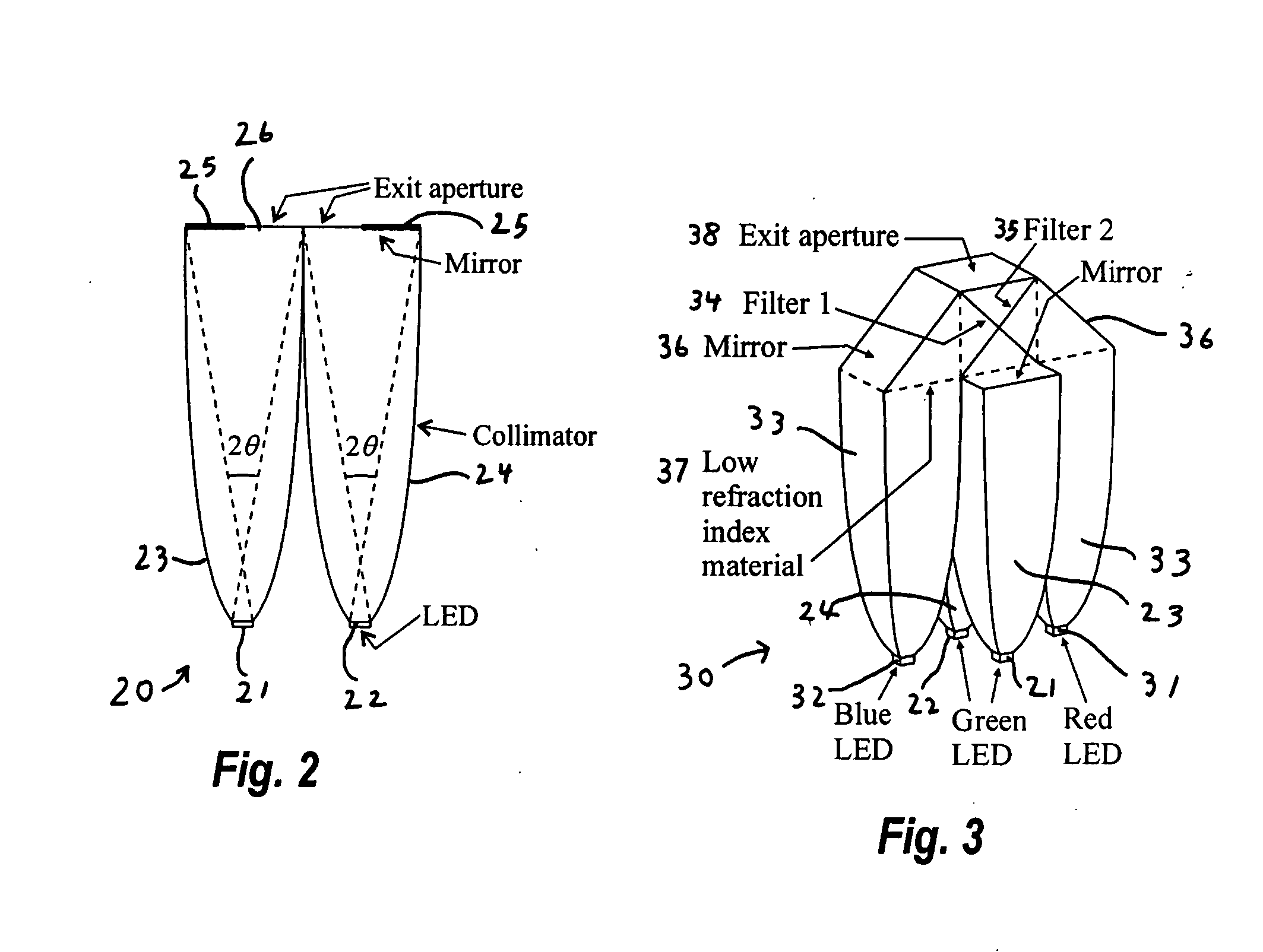
[0037]FIG. 2 shows a device, indicated generally by the reference numeral 20, that combines the output of two LEDs 21, 22 of the same or different colors. In the case where the colors are different there will be spatial separation of colors. This may or may not be an issue depending on the application. On each of the LEDs (in this case one on the left and one on the right) there is a collimator 23, 24. At the top of each collimator there is a mirror 25 that covers a fraction of the exit aperture 26 of the collimator 23, 24. As shown in FIG. 2, each collimator 23, 24 is a compound parabolic concentrator, with its intensity distribution being nearly invariant across its aperture, so that etendue is in direct proportion to the exposed proportion of the exit aperture area. In the c...


PUM


Abstract

An embodiment of an optical manifold has first and second collimators, each arranged to receive light from a source and transmit the light to an exit port of the collimator, and a separator arranged to emit some of the light from the exit ports of the first and second collimators and to recycle some of the light into the collimators. Another embodiment has at least three collimators of substantially equal length and having central axes, respective light sources at entry ports of the collimators, the collimators being arranged with their central axes parallel and with their light sources in a common plane and reflectors positioned to direct light from exit ports of the collimators to a selectively reflective component that guides all the light into a common exit beam.

Description

CROSS-REFERENCE TO RELATED APPLICATIONS [0001] This application claims benefit of U.S. Provisional Patent Application No. 60 / 822,207, filed Aug. 11, 2006, which is incorporated herein by reference in its entirety. [0002] This application is a continuation in part of U.S. patent application Ser. No. 11 / 115,055, filed Apr. 25, 2005, (publication no. US 2005 / 0243570 A1) which is incorporated herein by reference in its entirety. [0003] Application Ser. No. 11 / 115,055 claims the benefit of U.S. Provisional Patent Application No. 60 / 658,713, filed Mar. 3, 2005, entitled OPTICAL MANIFOLDS FOR LIGHT-EMITTING DIODES, which is incorporated by reference herein in its entirety. [0004] Application Ser. No. 11 / 115,055 claims the benefit of U.S. Provisional Patent Application No. 60 / 614,565, filed Sep. 29, 2004, entitled OPTICAL MANIFOLDS FOR LIGHT-EMITTING DIODES, which is incorporated by reference herein in its entirety. [0005] Application Ser. No. 11 / 115,055 claims the benefit of U.S. Provision...

Claims


Application Information

Patent Timeline
IPC IPC(8): G02B27/30F21V9/16
CPCF21K9/00F21Y2101/02G02B6/0018G02B6/0028G02B19/0028G02B27/143G02B27/149H04N9/315G02B19/0066G02B27/1006F21K9/68F21Y2115/10
Inventor CHAVES, JULIO C.FALICOFF, WAQIDIMINANO, JUAN CARLOSBENITEZ, PABLOPARKYN, WILLIAM A. JR.
Owner LIGHT PRESCRIPTIONS INNOVATORS
Why Eureka
Try Eureka