Viewing angle magnification liquid crystal display unit

a liquid crystal display and magnification technology, applied in the field of viewing angle magnification liquid crystal display, can solve the problems of poor light utilization efficiency, high cost, poor color reproducibility, etc., and achieve the effects of high contrast, good display quality, and good color reproducibility

Inactive Publication Date: 2008-01-08
NITTO DENKO CORP
View PDF50 Cites 34 Cited by
  • Summary
  • Abstract
  • Description
  • Claims
  • Application Information

AI Technical Summary

Benefits of technology

[0181]A viewing angle magnification liquid crystal display of this invention condenses emitted lights only in view fields each having the highest contrast and good color reproducibility. As a result, a picture image obtained from the liquid crystal display can be brighter only in view fields good in display quality.
[0182]As for a thickness, a functional film realizing collimation is 200 μm or less and if a thickness of a support base material used in manufacture is excluded, an optical film with a practically sufficient performance is obtained on the order of tens of μm. This thickness range has not been realized with a material for geometric optics such as conventionally used lens, prism and others. That is, this is a great advantage as compared with a viewing angle magnification system having been conventionally proposed.
[0183]Adoption of this system to make uniform lights with good display characteristic in a region in the vicinity of the front and to magnify a view angle enables a liquid crystal display high in durability to gray scale inversion and a change in hue and good in viewing angle characteristic to be obtained. In this system, a cell of the liquid crystal display acquires a sufficiently high characteristic even in a case where no compensation film is applied to an ordinary TN liquid crystal that has been conventionally available and no necessity arises for liquid crystal alignment control or a special retardation plate provided at high cost.
[0184]According to a viewing angle magnification liquid crystal display of this invention, a thin type viewing angle magnification system, which has not been conventionally available, can be, in such a way, realized with ease at a low cost.

Problems solved by technology

In a liquid crystal display of this kind, however, a backlight technique to obtain collimated lights is difficult.
In a system proposed in the above patent literatures and others, for example, there have been many problems in practical aspects since a backlight system is thick, poor in light utilization efficiency and high in cost.
In the second method, however, a light loss is large and therefore, the method has not been suited for use in liquid crystal display.
And by means of a shape of a backlight guide member is limited within a range of the order of ±40°, which is short in ability for use in a viewing angle magnification system of a liquid crystal display.
In the method, however, there has been a problem in brightness because of a large absorption loss in the course of collimation.
That is, one of a thickness, brightness and a parallelism of obtained lights have to be sacrificed due to a requirement from design, resulting in many of problems for putting it into practical use.
In these methods, however, a thickness and a weight increase greatly, which negates to establish a position as a useful means in applications other than a projector or the like.
In a collimation means using a shielding louver, a microlens array, a prism or the like, a moiré occurs between a fine structure and pixels of the liquid crystal display, thereby having disabled a good display to be obtained.
In order to prevent a moiré, it is possible to insert a diffusion means, whereas a problem arises that a parallelism of obtained collimated lights is degraded, which has been a problem against putting into practical use.
In a case where a structure having regularity such as a microlens array, a microprism or the like is employed in a collimated light diffusing means, interference occurs with the fine structure thereof.
For example, if a collimating means adopts a size of a structure not interfering with the liquid crystal pixels, a collimated light diffusing means similarly adopts a size of a structure not interfering with the liquid crystal pixels; therefore, both means result in having the sizes interfering with each other.
This applies to a contrivance of angles and arrangement in a similar way, which has narrowed a range of an allowable design and restricted a selectable optical system within an extremely small range.
In such a way, a viewing angle magnification system consisting of a collimating means and a collimated light diffusing means has limited options in design because of an optical problem caused by respective fine structures, having lead to difficulty putting the system into practical use.
Therefore, a problem has remained that is related to design and manufacture of a film selectively functioning for a specific wavelength.
In addition, in a case where a band pass filter is of an evaporated interference film, even a reliability problem has existed that a wavelength characteristic alters due to a change in refractive index of a thin film in a humidified environment.
A material of this kind is high in a front transmittance, while an obliquely incident light cannot be perfectly reflected and removed off.
Therefore, in a case where the system is disposed on an actual diffusion backlight light source, a light condensing function cannot be sufficiently satisfied.
Many of hologram materials are soft and weak, having lead to many problems related to reliability.

Method used


Image

  • Viewing angle magnification liquid crystal display unit
  • Viewing angle magnification liquid crystal display unit
  • Viewing angle magnification liquid crystal display unit

Examples


example 1

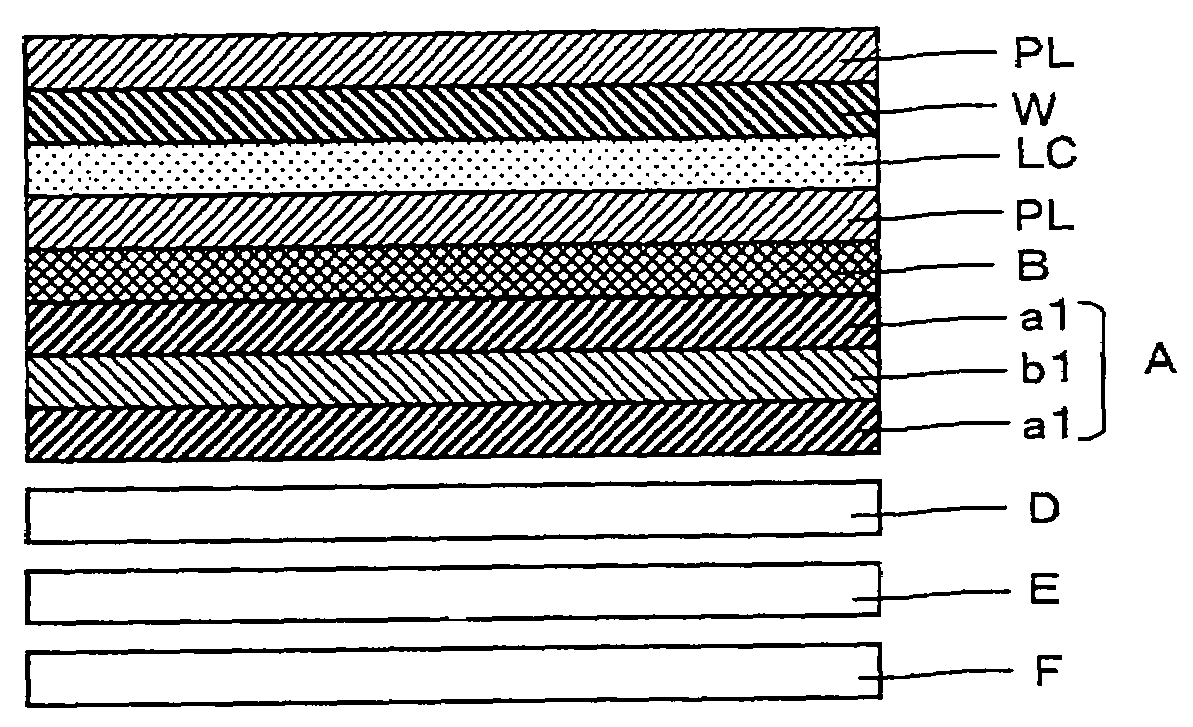
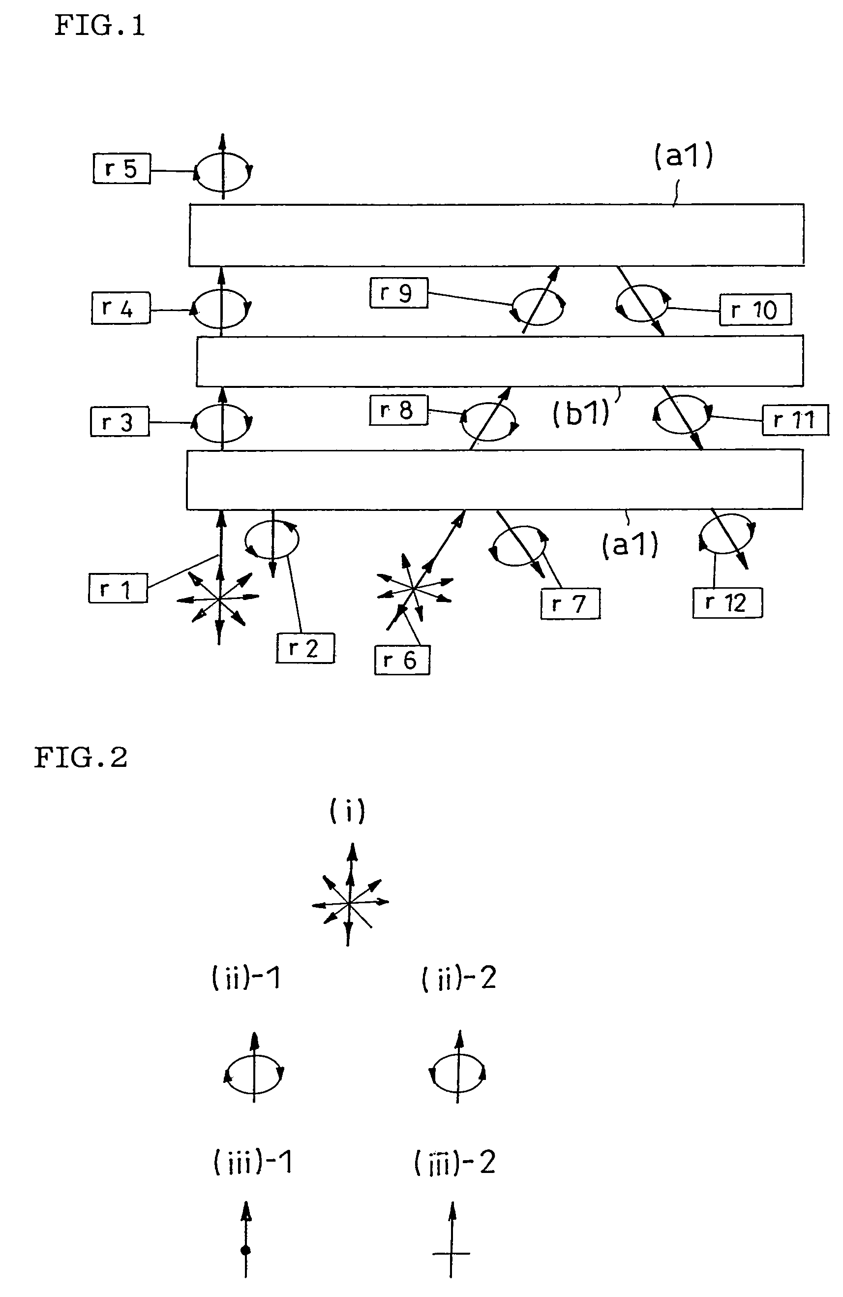
(Preparation of Circular Polarization Type Reflection Polarizer (a1))

[0292]The circular polarization type reflection polarizer (a1) was prepared with a polymerizable nematic liquid crystal monomer and a chiral agent sold on the market. A used cholesteric liquid crystal was obtained from a mixture of a polymerizable mesogen compound and a polymerizable chiral agent, wherein LC242 manufactured by BASF Japan Ltd. was used as the polymerizable mesogen compound, and LC756 manufactured by BASF Japan Ltd. was used as the polymerizable chiral agent.

[0293]The polymerizable mesogen compound and the polymerizable chiral agent were mixed in a mixing ratio of 5 to 95 in weight ratio so that a central wavelength in selective reflection of an obtainable cholesteric liquid crystal was about 550 nm. The obtained cholesteric liquid crystal had a central wavelength in selective reflection was 545 nm and a selective reflection wavelength bandwidth was about 60 nm.

[0294]A detailed method was as follows:...

example 2

(Preparation of Positive C Plate)

[0307]A retardation layer (b1 as a positive C plate) having a front retardation of O and a retardation in an oblique direction of a value was prepared with a polymerized liquid crystal. Used as a polymerizable liquid crystal compound was a polymerizable nematic liquid crystal monomer A expressed by the following chemical formula 1:

[0308]

[0309]A detailed method was as follows. The polymerizable nematic liquid crystal monomer A was dissolved in cyclopentane (at 30 wt %) and a reaction initiator (IRGACURE 907 manufactured by Ciba Specialty Chemicals. at 1 wt % relative to the monomer A) was added to the monomer A to prepare a solution. An vertical alignment film in use was formed by coating a cyclohexane solution (at 0.1 wt %) of a release agent (octadecyltrimethoxysilane) on a polyethylene terephthalate film: LUMIRROR (a thickness of 75 μm) manufactured by TORAY INDUSTRIES INC. to dry the coat.

[0310]The polymerizable nematic liquid crystal monomer A so...

example 3

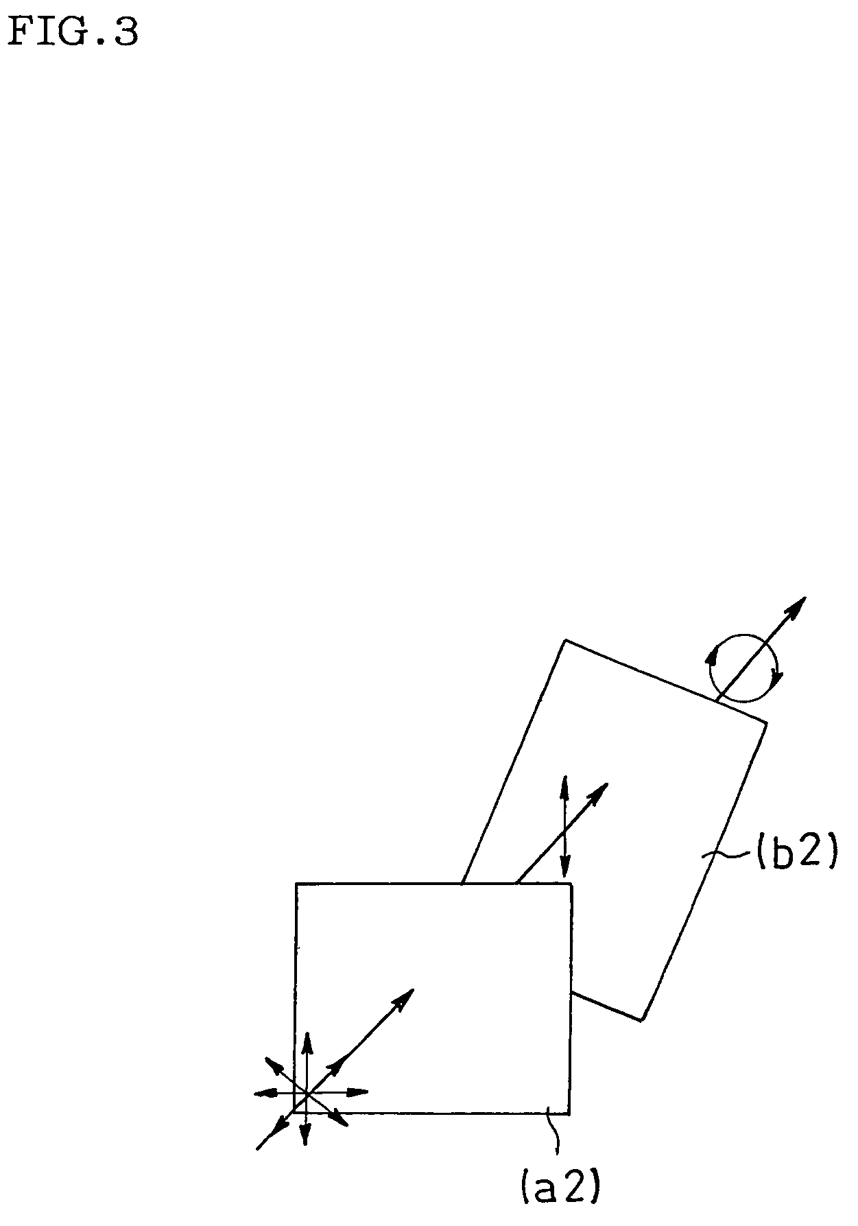
(Preparation of Linear Polarization Type Reflection Polarizer (a2))

[0313]A multilayer film with 20 layers was obtained by alternately controlling thicknesses of thin films with a feed block method so that polyethylene naphthalate (PEN) / naphthalene dicarboxylate-terephthalate copolyester (co-PEN) were alternately laminated. The multilayer film was uniaxially stretched. A stretching temperature was about 140° C. and a stretch ratio was about threefold in the TD direction. A thickness of each of thin layers in the obtained stretched film was roughly on the order of 0.1 μm. Five stretched films of the obtained 20 layer laminate films were further laminated into a five composite layer laminate including 100 layers in total, thereby obtaining the linear polarization type reflection polarizer (a2). The linear polarization type reflection polarizer (a2) had a reflection function exerted on linearly polarized light in a wavelength band of 500 nm or more and 600 nm or less.

(Preparation of Pol...


PUM

PropertyMeasurementUnit
wavelength rangeaaaaaaaaaa
angleaaaaaaaaaa
angleaaaaaaaaaa

Abstract

A viewing angle magnification liquid crystal display of this invention comprising: at least a backlight system containing a polarization element (A) obtained by disposing a retardation layer (b) between at least two layers, included in a reflection polarizer (a), and having respective selective reflection wavelength bands of polarized light superimposed on each other to conduct collimation for a diffusion light source; a liquid crystal cell transmitting collimated lights; a polarizing plate disposed on both sides of the liquid crystal cell; and a viewing angle magnifying layer disposed on the viewer side of the liquid crystal cell to diffuse transmitted light. The liquid crystal display can realize a thin type and have a wide viewing angle.

Description

TECHNICAL FIELD[0001]The present invention relates to a viewing angle magnification liquid crystal display.BACKGROUND ART[0002]As a system for magnifying a viewing angle of a liquid crystal display, there has been known a method in which lights from backlight are collimated, and only lights in the vicinity of the front, good in contrast and tone are extracted and diffused to thereby obtain a display with the same quality as in the vicinity of the front even when viewed at any angle (see, for example, publications of JP-A Nos. 10-333147 and 10-25528).[0003]In a liquid crystal display of this kind, however, a backlight technique to obtain collimated lights is difficult. In a system proposed in the above patent literatures and others, for example, there have been many problems in practical aspects since a backlight system is thick, poor in light utilization efficiency and high in cost.[0004]In an ordinary TN type liquid crystal display without a viewing angle compensating film, a regio...

Claims


Application Information

Patent Timeline
Patent Type & Authority Patents(United States)
IPC IPC(8): G02F1/1335G02B5/30G02F1/13357G02F1/13363
CPCG02B5/3041G02F1/133504G02F1/133536G02F2001/133507G02F1/13363G02F1/133634G02F1/13362G02F1/133507G02F1/1335
Inventor HARA, KAZUTAKATAKAHASHI, NAOKIMIYATAKE, MINORU
Owner NITTO DENKO CORP
Why Eureka
Try Eureka