Projection screen and projection system comprising the same

a projection screen and projection system technology, applied in the field of projection systems, can solve the problems of inability to satisfactorily provide inability to reduce the brightness difference between white and black, and inability to achieve good image display performance of the above-described conventional projection screen. achieve the effect of suppressing influence, lowering image visibility, and improving image contras

Inactive Publication Date: 2007-01-09
DAI NIPPON PRINTING CO LTD
View PDF8 Cites 34 Cited by
  • Summary
  • Abstract
  • Description
  • Claims
  • Application Information

AI Technical Summary

Benefits of technology

[0018]The present invention has been accomplished in the light of the above-described problem. An object of the present invention is, therefore, to provide a projection screen capable of sharply displaying an image even under bright environmental light and of providing improved image visibility, and a projection system comprising such a projection screen.

Problems solved by technology

It is however not easy for the above-described conventional projection screens to show good image display performance under bright environmental light because they reflect not only imaging light but also environmental light such as sunlight and light from lighting fixtures.
However, since the above-described conventional projection screen reflects both imaging light and environmental light such as sunlight and light from lighting fixtures without distinction, both the white- and black-indication parts get lighter, and differences in brightness between white and black become small.
For this reason, the conventional projection screen cannot satisfactorily provide good image display unless the influence of environmental light such as sunlight and light from lighting fixtures on the projection screen is suppressed by using a means for shading a room, or by placing the projection screen in a dark environment.
However, holograms have wavelength selectivity but no polarization selectivity, so that the projection screens using holograms can display images only with limited sharpness.
Moreover, because of production problems, it is difficult to produce large-sized projection screens by making use of holograms.
However, in the projection screen described in Patent Document 1, since the cholesteric liquid crystal is in the sate of planar orientation and causes specular reflection when reflects light, it is difficult to recognize the reflected light as an image.
However, in the projection screens described in Patent Documents 1 and 2, the characteristic nature of light of the three primary colors (red (R), green (G), and blue (B)) contained in imaging light which a conventional projector projects is not taken into account at all.

Method used


Image

  • Projection screen and projection system comprising the same
  • Projection screen and projection system comprising the same
  • Projection screen and projection system comprising the same

Examples


examples

[0169]A specific example of the above-described embodiments will now be given below.

example

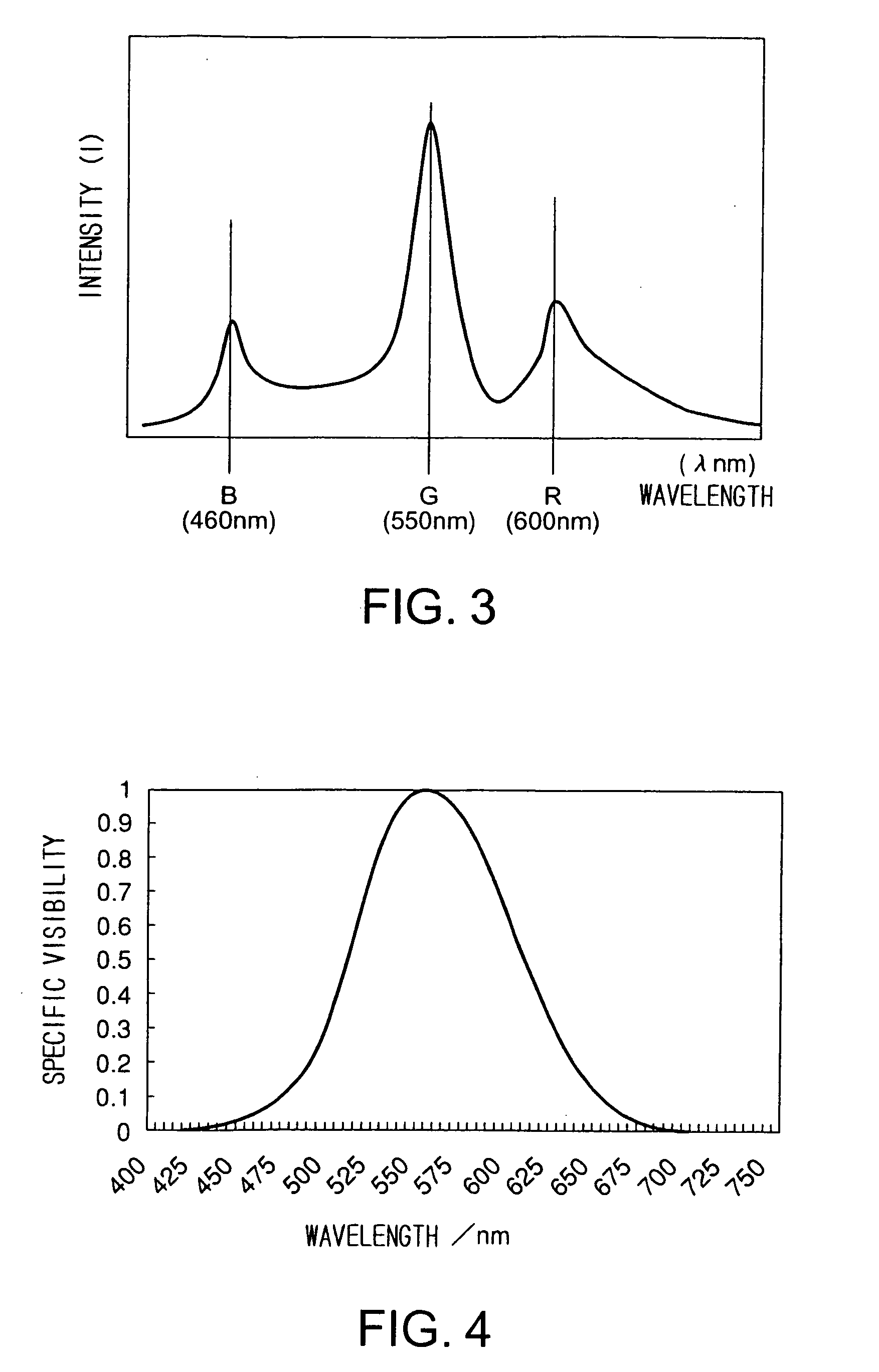
[0170]A first cholesteric liquid crystal solution having a selective reflection wave range with a center wavelength of 450 nm was prepared by dissolving, in cyclohexanone, a monomer-containing liquid crystal consisting of a main component that was an ultraviolet-curing, nematic liquid crystal (94.7% by weight) and a chiral agent (5.3% by weight).

[0171]A liquid crystal containing a compound represented by the above chemical formula (2-xi) was used as the nematic liquid crystal.

[0172]A compound represented by the above chemical formula (5) was used as the polymerizable chiral agent.

[0173]To the first cholesteric liquid crystal solution was added 5% by weight of a photopolymerization initiator available from Ciba Specialty Chemicals K.K., Japan.

[0174]By a bar coating method, the above-prepared first cholesteric liquid crystal solution was applied to a substrate, a 200 mm×200 mm black-colored PET film coated with an adherent layer (Lumirror / AC-X manufactured by Panack Co., Ltd., Japan)....


PUM

PropertyMeasurementUnit
center wavelengthsaaaaaaaaaa

Abstract

A projection screen including a polarized-light selective reflection layer having a cholesteric liquid crystalline structure that causes selective diffuse-reflection of a specific polarize-light component, and a substrate for supporting the polarized-light selective reflection layer. The polarized-light selective reflection layer includes three partial selective reflection layers that are layered one over another, and each partial selective reflection layer has a cholesteric liquid crystalline structure that causes selective diffuse-reflection of a specific polarized light component. In the polarized-light selective reflection layer, three partial selective reflection layers that reflect light in the green (G) color wave range, red (R) color wave range, and blue (B) color wave range are layered in this order, the firstly-mentioned partial selective reflection layer being on the observation side. Namely, the partial selective reflection layer for selectively reflecting light in the green (G) color wave range is arranged as the outermost layer on the observation side.

Description

BACKGROUND OF THE INVENTION[0001]1. Field of the Invention[0002]The present invention relates to a projection system in which imaging light emitted from a projector is projected on a projection screen to produce thereon an image. More particularly, the present invention relates to a projection screen capable of sharply displaying an image and of providing high image visibility, and to a projection system comprising such a projection screen.[0003]2. Description of Related Art[0004]A conventional projection system is usually as follows: imaging light emitted from a projector is projected on a projection screen, and viewers observe the light reflected from the projection screen as an image.[0005]Typical examples of materials for projection screens for use in such conventional projection systems include white-colored paper or cloth materials, and plastic films coated with white inks that diffuse light. Besides, high-quality projection screens that comprise diffusing layers containing be...

Claims


Application Information

Patent Timeline
Patent Type & Authority Patents(United States)
IPC IPC(8): G03B21/60C09K19/02G02B13/20G02B27/28G02B5/02G02B5/30G02F1/1335G03B21/56
CPCG03B21/56
Inventor UMEYA, MASANORI
Owner DAI NIPPON PRINTING CO LTD
Why Eureka
Try Eureka