Method and apparatus for coupling radiation from a stack of diode-laser bars into a single-core optical fiber

Inactive Publication Date: 2006-03-07
COHERENT INC
View PDF33 Cites 34 Cited by
  • Summary
  • Abstract
  • Description
  • Claims
  • Application Information

AI Technical Summary

Benefits of technology

[0012]An optical arrangement for focusing the combined laser-radiation beams into the optical fiber includes a lens having positive optical power in the fast axis and zero optical power in the slow axis, and another lens having positive optical power in the slow axis and zero optical power in the fast axis. Alignment of the combined beams may be effected by arranging and aligning the diode-laser bars such that each of the first and second emitters are aligned in the fast axis direction. In a case where the emitters can not be accurately so aligned, an alignment plate may be provided for each diode-laser bar. The alignment plate is disposed between the diode-laser bar and the composite prism and is rotatable about the fast-axis direction for laterally displacing the path of the emitted beams in the slow-axis direction. Providing such al

Problems solved by technology

In the slow axis, however, the beams collectively have a poor beam-quality that is

Method used


Image

  • Method and apparatus for coupling radiation from a stack of diode-laser bars into a single-core optical fiber
  • Method and apparatus for coupling radiation from a stack of diode-laser bars into a single-core optical fiber
  • Method and apparatus for coupling radiation from a stack of diode-laser bars into a single-core optical fiber

Examples


Embodiment Construction

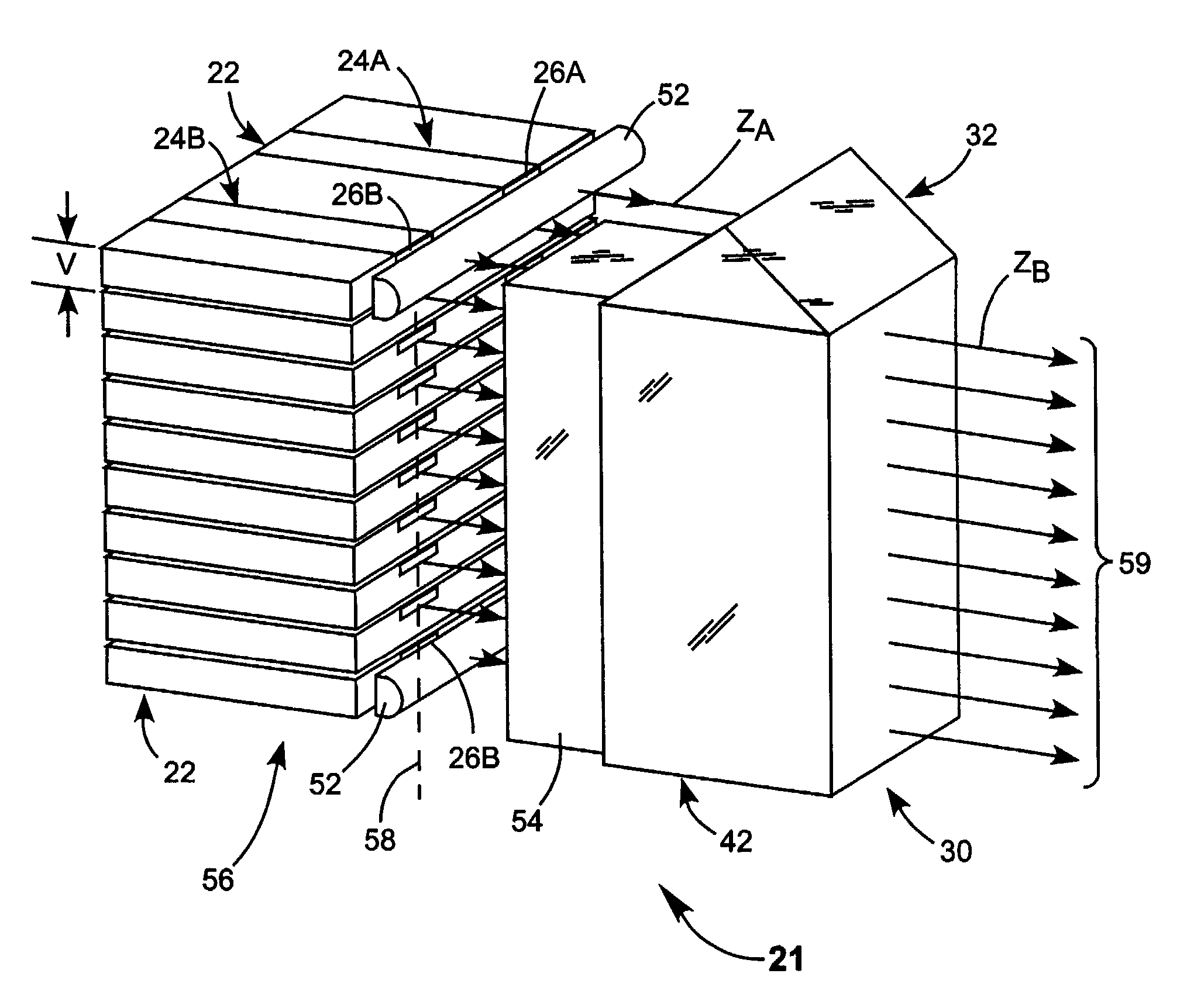
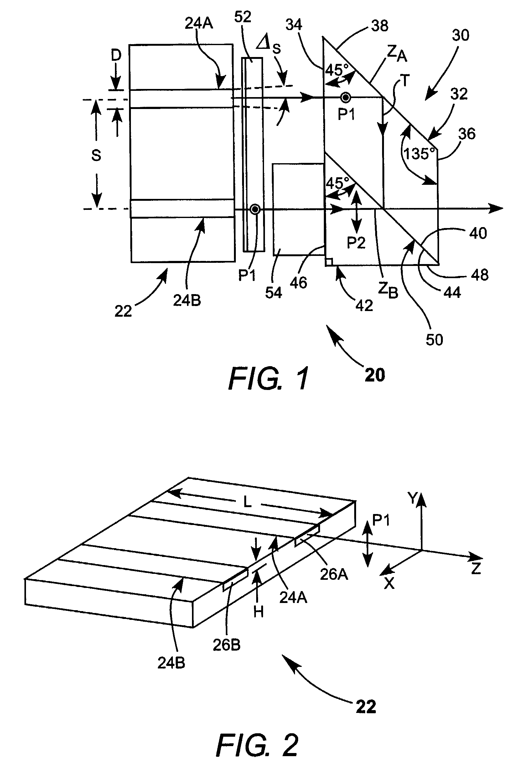
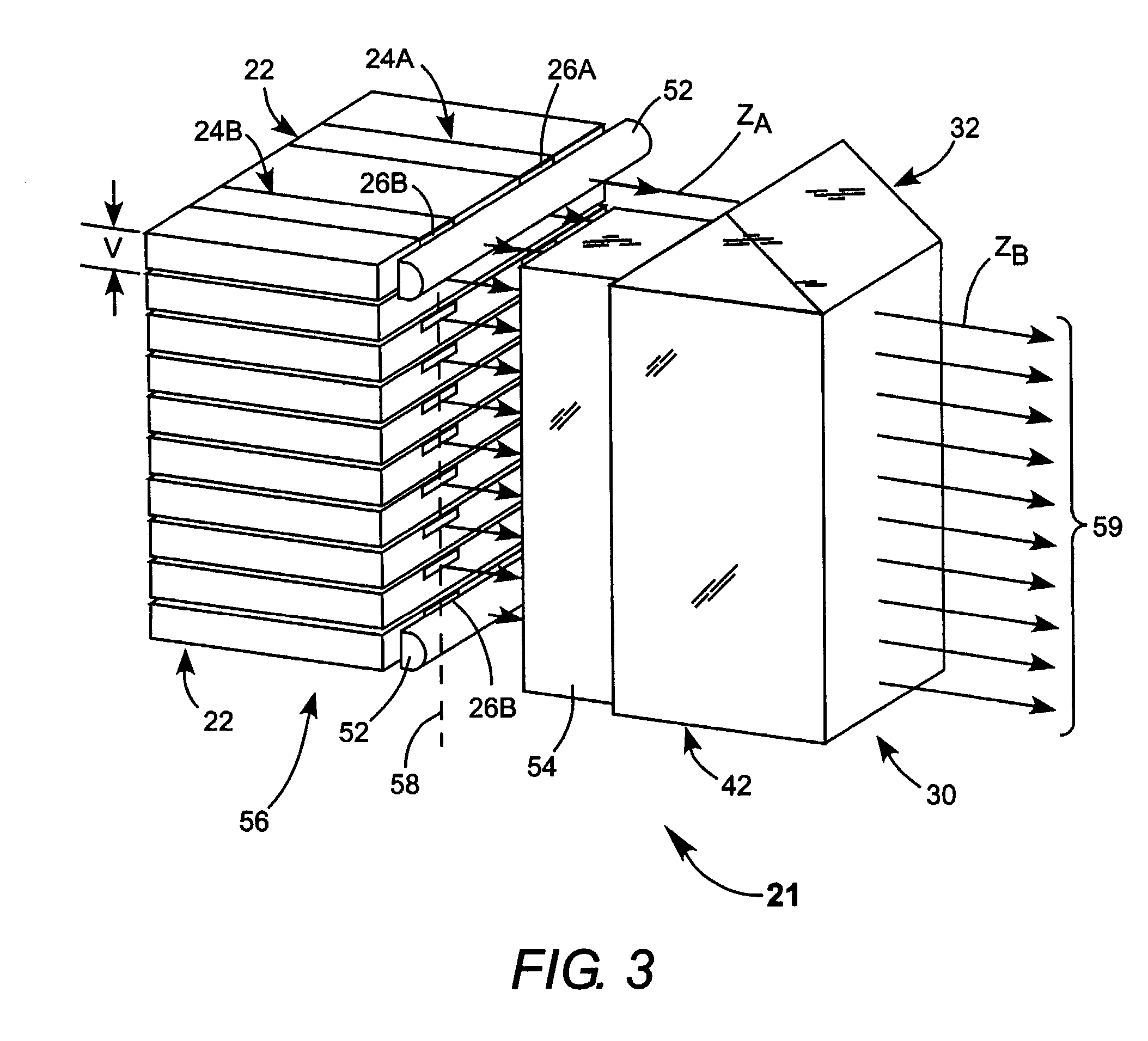
[0027]Turning now to the drawings, wherein like features are designated by like reference numerals, FIG. 1 schematically illustrates a preferred embodiment 20 of beam combining apparatus in accordance with the present invention. Apparatus 22 includes a diode-laser bar or array having two emitters 24A and 24B. Referring additionally to FIG. 2, emitters 24A and 24B emit laser-radiation from emitting-apertures 26A and 24B respectively, each having a height H, and a with D. The emitters have a length L about equal the width of diode-laser bar 22. Emitters 24A and 24B are spaced apart center-to-center by a distance S. Height H is typically on the order of about 1.0 micrometers (μm). Width D is preferably between about 50 and 1000 μm. Emitters having a width in this range are often referred to by practitioners of the art as broad-area emitters, or broad-aperture emitters. Such emitters can deliver up to about 20 Watts (W) of power per emitter.

[0028]Each emitter 24 emits laser-radiation in...


PUM


Abstract

A method of coupling laser-radiation into an optical fiber includes providing a stack of diode-laser bars and first and second parallel mirrors, the second mirror is selectively reflective only for one polarization plane of the laser-radiation. Each of the diode-laser bars includes at least two spaced-apart diode-laser emitters each emitting a plane-polarized beam of laser-radiation having a fast axis and a slow axis. The laser-radiation beams are collimated in the fast axis by a cylindrical lens located in front of each bar. In one arrangement the polarization orientation of one collimated beam from each diode-laser is rotated by 90 degrees and transmitted through the selectively-reflective mirror. The other collimated beam from each diode-laser bar is reflected onto the selectively-reflective mirror by the first mirror and reflected from the selectively-reflective mirror such that the reflected beam combines with the transmitted beam to form a combined beam. As many combined beams are formed as there are diode-laser bars in the stack. These combined beams are focused into an entrance face of the optical fiber.

Description

TECHNICAL FIELD OF THE INVENTION[0001]The present invention relates generally to coupling laser-radiation from two-dimensional diode-laser arrays into a single-core optical fiber. The invention relates in particular to coupling radiation from a stack of two-emitter diode-laser bars by combining beams from each emitter to form plurality of parallel beams aligned in the fast axis of the diode-laser bars and focusing the plurality of beams into the single-core optical fiber.DISCUSSION OF BACKGROUND ART[0002]Laser-radiation from diode-laser arrays is frequently used for optically pumping solid-state lasers. The diode-laser array may be a one-dimensional (linear) array or a two-dimensional array. Typically, a one-dimensional array of diode-lasers is made by forming a plurality of diode-lasers (emitters) in a common substrate. This is commonly referred to as a diode-laser bar. A plurality of such bars can be stacked to form a two-dimensional diode-laser array.[0003]In a solid state-laser,...

Claims


Application Information

Patent Timeline
IPC IPC(8): G02B6/34G02B6/42G02B27/28
CPCG02B6/4206G02B6/4208G02B6/425G02B27/283G02B6/4214H01S5/4012
Inventor ANIKITCHEV, SERGUEI G.REKOW, MATHEW N.
Owner COHERENT INC
Why Eureka
Try Eureka