LED light unit

a technology of led light and led light, which is applied in the direction of lighting support devices, lighting and heating apparatuses, instruments, etc., can solve the problems of insufficient narrowness, difficult to get the apparent emitted light, and rapid reduction of light intensity

Inactive Publication Date: 2008-03-27
COAST CUTLERY
View PDF54 Cites 41 Cited by
  • Summary
  • Abstract
  • Description
  • Claims
  • Application Information

AI Technical Summary

Benefits of technology

[0013]In configurations with a reflector, the LED may be disposed in front of or opposite the reflector and emits light into the reflector. The reflected light that is emitted from the lig...

Problems solved by technology

The included angle of the light from an LED is much narrower than an incandescent bulb, but it is still not sufficiently narrow to form a beam, and the intensity of the light diminishes quickly with distance.
It is more ...

Method used


Image

  • LED light unit
  • LED light unit
  • LED light unit

Examples


first embodiment

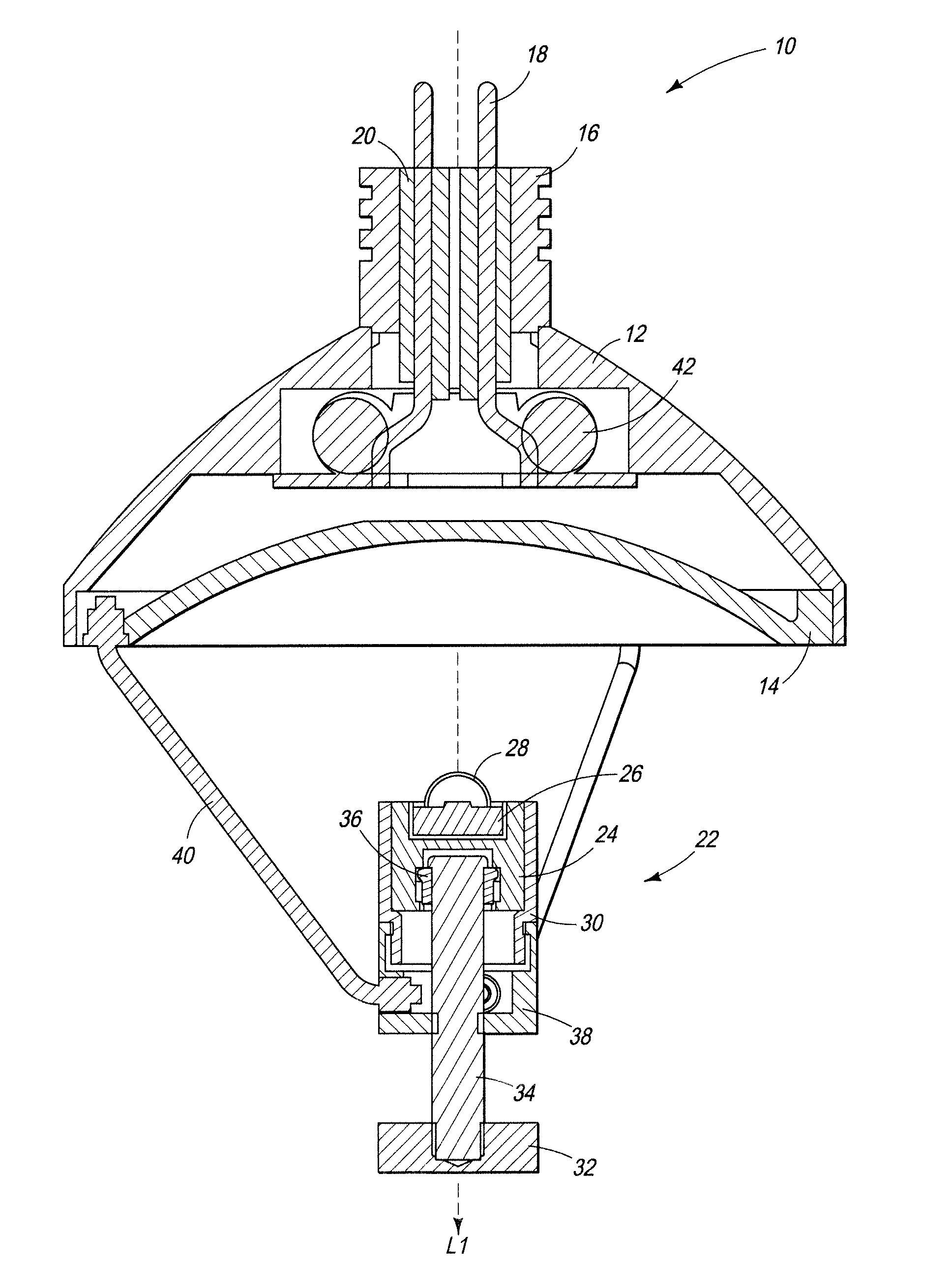
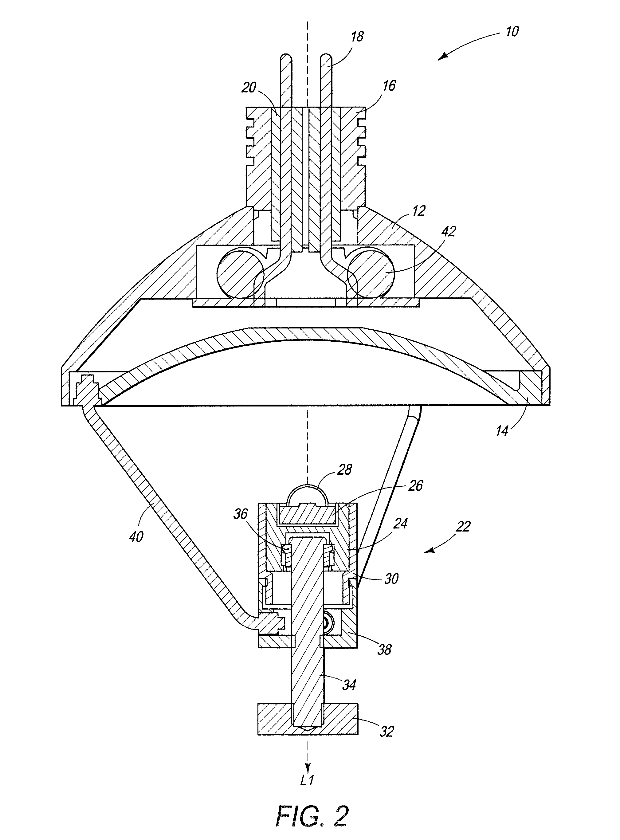
[0033]In an alternate configuration of the first embodiment, LED assembly 22 may support a plurality of LEDs in LED base 24. In another alternate configuration, LED 26 may not be movable in LED assembly 22 and may be fixed in place.

Embodiment of FIGS. 4-7

second embodiment

[0034]FIG. 4 is a cross section side view of an LED unit shown generally as 50. In this embodiment, the light emitter is a substantially conical light guide made from a translucent plastic or other light permeable material. The phrase “substantially conical” is intended to cover a perfectly conical shape as well as one that is somewhat rounded as shown in FIG. 4.

[0035]For clarity, similar numbering may be used in this and later figures as was used in previous figures. LED unit 50 again includes a unit housing 12, a plug base 16 retaining plug pins 18 and insulator 20, an LED 26 operably connected to plug pins 18. LED unit 50 may further include a power supply 42 and a support frame 52 configured to align and support internal components, a light guide 54 and a front cover 56. LED 26 may be mounted on and supported by power supply 42.

[0036]As depicted in FIG. 4, power supply electronics 42, support frame 52, LED 26 and elongated, substantially conical light guide 54 assemble into unit...


PUM


Abstract

A lighting unit is provided including at least one LED, a plug for connecting the unit to an appliance and a light emitting element. The lighting unit may include electronic components to condition power from the appliance. The light emitting element may comprise a reflector where the LED emits light into the reflector and the light is collimated by the reflector and emitted from the unit. The position of the LED may be adjustable so the LED moves closer or farther from the reflector. Light is emitted from the unit in a narrower or wider beam in response to moving the LED. Alternately, the light emitting element may be an optical waveguide with a receiving end proximate to the LED emitting face and an emitting face away from and opposite the receiving face. The optical waveguide may collimate the wide angle of light emitted by the LED to form a narrow, directed beam.

Description

FIELD OF THE INVENTION[0001]The present invention relates to light units using light emitting diodes (LEDs) as the light source, which may be used to replace halogen, incandescent or fluorescent bulbs.BACKGROUND OF THE INVENTION[0002]New high intensity LEDs have adequate light intensity and illumination to replace existing lighting, such as fluorescent, halogen and incandescent bulbs, while decreasing package size and power consumed. New high brightness LEDs use a more powerful chip to generate a much brighter light. Manufacturers are producing high brightness LED packages in a variety of forms. Originally these LEDs were directly substituted for standard incandescent bulbs. LEDs emit light from a plane rather than radiating omnidirectionally from an incandescent filament. The included angle of the light from an LED is much narrower than an incandescent bulb, but it is still not sufficiently narrow to form a beam, and the intensity of the light diminishes quickly with distance.[0003...

Claims


Application Information

Patent Timeline
IPC IPC(8): F21V7/00F21V8/00
CPCF21V7/0008F21V14/02F21K9/13F21Y2101/02F21K9/58F21V21/26F21K9/23F21K9/65F21Y2115/10
Inventor BRANDS, DAVID C.YEE, RICHAROPOLKA, RAINER
Owner COAST CUTLERY
Why Eureka
Try Eureka