Focusing lens system

a technology of focusing lens and lens body, which is applied in the field of lenses, can solve the problems of limited capacity of lenses, and achieve the effect of facilitating the removal of mold

Active Publication Date: 2013-02-12
COAST CUTLERY
View PDF70 Cites 34 Cited by
  • Summary
  • Abstract
  • Description
  • Claims
  • Application Information

AI Technical Summary

Problems solved by technology

Typically, lenses are limited in their capacity to combine a maximum intensity for a spot beam with a substantial uniformity for a wide beam.

Method used


Image

  • Focusing lens system
  • Focusing lens system
  • Focusing lens system

Examples


Embodiment Construction

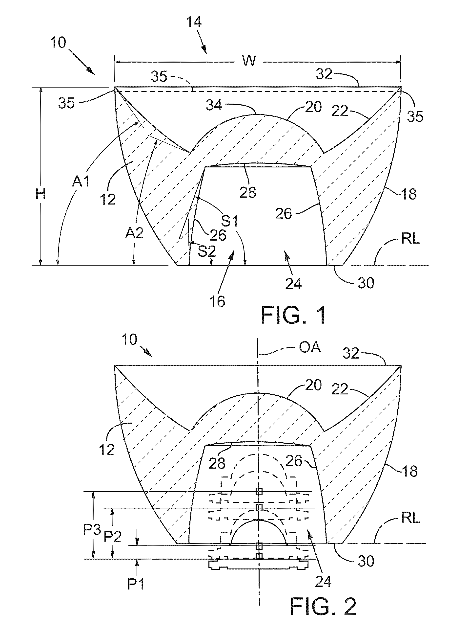
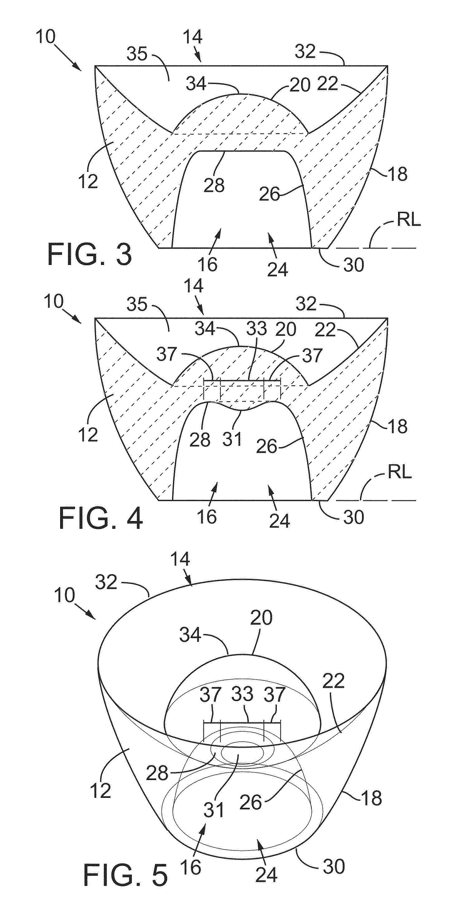
[0026]FIG. 1 shows a lens 10 for focusing light. Lens 10 may include a lens body 12 with a front face 14, a rear void, such as well 16, and a side surface 18 that extends between front face 14 and rear well 16. Front face 14 includes a central surface 20 surrounded by an annular surface 22 that may define in cross-section a concave curve. Rear well 16 defines a space 24 within which an LED or other light source may be adjusted in position (see e.g., FIG. 2).

[0027]Well 16 is typically defined by a void sidewall 26 and a base 28. Sidewall 26 preferably defines in cross-section, as shown in FIG. 1, a concave curve. Base 28, in this embodiment, also defines in cross-section a concave curve. Rear well 16 may include a rear rim 30, which as shown in FIG. 1, may be understood to define a reference line RL.

[0028]The shape of the concave curves in the base and sidewall may be any shape suitable for manufacture and use. The curve of sidewall 26 is typically a Bezier curve. A preferred Bezier ...


PUM


Abstract

A lens for a flashlight or other lighting unit provides for focusing light from a source, such as an LED, to provide a light beam adjustable between a spot beam and a wide beam. The lens includes a lens body with a front face, a rear LED-receiving well, and a side surface extending between the front face and the rear well. The front face includes a central surface surrounded by an annular concave surface. The rear well includes a space for the LED to be adjusted in position. The rear well space is defined by a concavely-curved sidewall and a concavely-curved base. The concave curvature of the sidewall and base may be Bezier curves.

Description

CROSS REFERENCE TO RELATED APPLICATIONS[0001]The present application is a continuation-in-part of U.S. patent application Ser. No. 12 / 572,910, filed Oct. 2, 2009, titled “Focusing Lens System,” the entire specification of which is hereby incorporated by reference in its entirety for all purposes, except those sections, if any, that are inconsistent with this specification.TECHNICAL FIELD[0002]The present invention relates to a lens for producing a beam of light from a light source, such as a light emitting diode (LED), in a flashlight or other lighting unit. The lens may be combined with an adjustment mechanism for varying the focus of the beam of light and may be housed in a structure supporting the lens, light source, and adjustment mechanism. Such structure may also include a power source, controls, interconnections, and electronics.BACKGROUND[0003]Lenses for flashlights and other lighting units have been provided in a variety of forms, generally having in common a shape that is ...

Claims


Application Information

Patent Timeline
Patent Type & Authority Patents(United States)
IPC IPC(8): F21L4/00
CPCF21L4/027F21V5/006F21V5/04G02B19/0061F21V14/065G02B19/0028F21V14/06F21V7/0091F21Y2101/02F21Y2115/10F21L4/005
Inventor GUPTA, ANURAGWINDOM, GREGORY DAVIDDUKELOW, OWEN W.
Owner COAST CUTLERY
Why Eureka
Try Eureka