Overhead vehicle storage system

a storage system and vehicle technology, applied in the field of overhead storage systems, can solve the problems of increasing traffic congestion, increasing traffic congestion, and increasing the difficulty of private vehicle parking spaces

Active Publication Date: 2008-03-27
GEBRR BECKER
View PDF34 Cites 100 Cited by
  • Summary
  • Abstract
  • Description
  • Claims
  • Application Information

AI Technical Summary

Benefits of technology

[0012]Further, the vehicle storage units allow for quick and easy stowage and retrieval of vehicles. Each vehicle storage unit includes rotating locks that connect an upper part of the storage unit to a lower frame. As such, the locks are disengaged to allow the upper part of the storage unit to be removed from the lower frame so that a vehicle can easily drive into or out of the storage unit. Likewise, the locks can be engaged and lock to allow the upper part of the storage unit to be fixed to the lower frame so that the overhead transfer unit can manipulate the entire storage unit.

Problems solved by technology

In many city and popular resort areas, private vehicle parking space has become an ever increasing problem.
The problem is increased in those areas where property values are extremely high such that construction of conventional ramp-like parking garages is not an economically viable prospect.
A direct problem that exists due to inadequate parking areas is increased traffic congestion.
As motorist are forced to continuously search for parking space, they continue to clog roadways and streets.
Lack of sufficient parking is thus a direct contributor to crowded streets and traffic congestion.
Many motorist do not have convenient sources of mass transit to go to their place of employment and many employers do not provide for parking expenses.
In city areas where parking spaces are limited, the cost of daily parking can be painfully expensive for many commuters.
In addition to the foregoing, in many areas, parking is at such a premium that apartment, condominium and home owners can not find adequate and safe street parking.
Even if a person can walk or take mass transit to and from a job, there is little or no safe areas to store personal or commercial vehicles for days or weeks at a time.

Method used


Image

  • Overhead vehicle storage system
  • Overhead vehicle storage system
  • Overhead vehicle storage system

Examples


Embodiment Construction

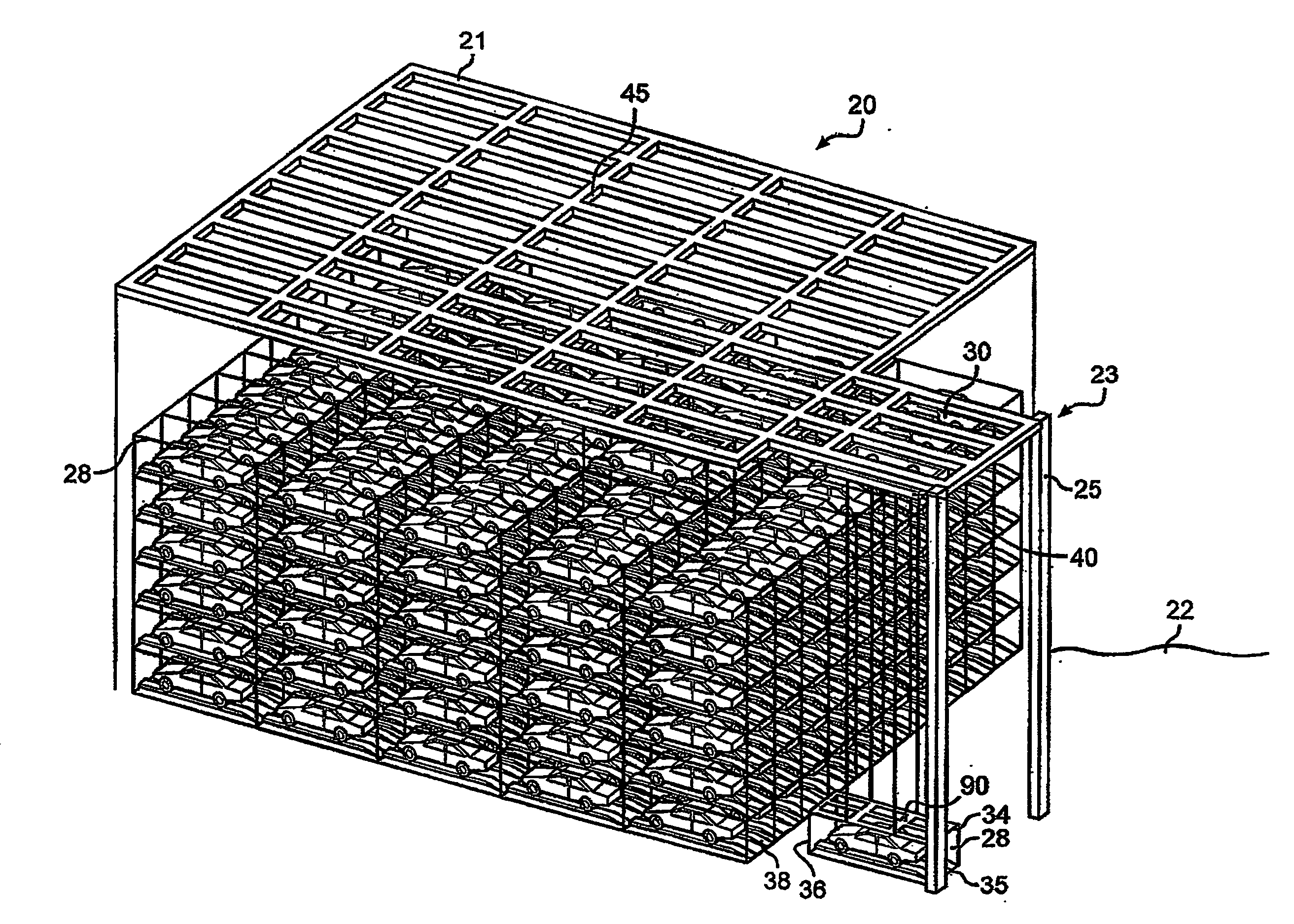
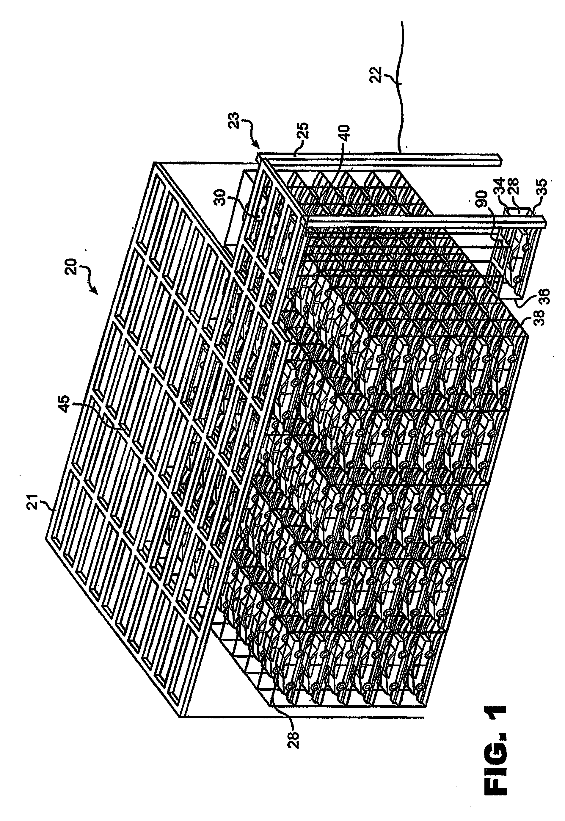
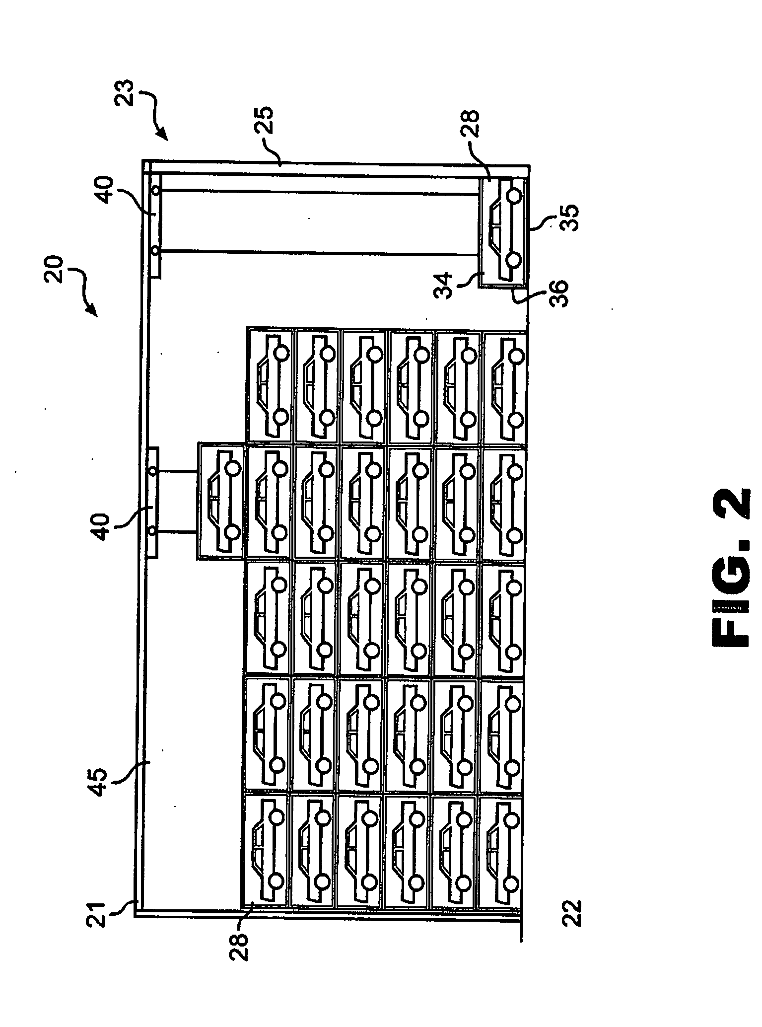
[0035]The present invention is directed to facilities and methods for safely and efficiently storing vehicles that allow maximum use to be made of limited areas adjacent roadways. The facilities of the invention are designed and configured to permit a maximum number of vehicles to be stored within a given space and yet easily accessible when needed for use. The facilities described herein are generally fully enclosed structures having outer side walls and roof that protect vehicles being stored from ambient weather conditions with the roof “R” being cut away and walls being removed to facilitate the description of the storage systems. Further, although the facilities described herein are preferably structured to permit vehicles, such as cars, trucks, and sport utility vehicles (SUVs), to be elevated directly from a road when being moved to storage and being directly lowered onto a road for use, the system and facilities may be used to elevate vehicles from trailers or to lower vehic...


PUM


Abstract

A system and method for the safe storage of vehicles wherein a storage structure is provided having a first section in which vehicles are stored in vertically oriented cells with each vehicle being carried within a vehicle storage unit such that the units may be stacked one upon another and wherein at least one transfer vehicle is provided for selectively engaging and conveying the vehicle storage units along an overhead grid track system between the first section and a second section wherein the grid track system is at least partially oriented over a roadway such that the at least one transfer vehicle may be used to either lift or lower a vehicle contained within a vehicle storage unit relative to the roadway and move the vehicle storage unit to and from a storage position in one of the vertical storage cells of the first section of the storage structure.

Description

CROSS-REFERENCE TO RELATED APPLICATIONS[0001]This application claims priority to U.S. provisional application No. 60 / 826,855, filed on Sep. 25, 2006, entitled “Overhead Vehicle Storage System,” which is hereby incorporated by reference in its entirety.BACKGROUND OF THE INVENTION[0002]1. Field of the Invention[0003]This application is directed to an overhead storage system for automotive vehicles wherein the vehicles are initially driven into storage units after which, with the vehicles locked in position, the storage units or racks are manipulated by one or more overhead transfer units that can lift or elevate the vehicles and maneuver them into a storage area wherein the storage units or racks are stacked in vertically oriented storage cells without the need to use conventional cranes and forklifts and in such a manner as to maximize storage space by eliminating the need for internal aisles for manipulating and / or vehicle handling equipment.[0004]2. Brief Description of the Related...

Claims


Application Information

Patent Timeline
Patent Type & Authority Applications(United States)
IPC IPC(8): E04H6/00
CPCE04H6/182B65G1/0464B65G1/0478E04H6/22E04H6/00
Inventor BENEDICT, CHARLES E.PFEIFER, BRIAN G.YATES, CHRISTIAN A.BLADEN, SCOTT K.LACKINGER, RICHARD E.DOBBS, JAMES R.
Owner GEBRR BECKER
Why Eureka
Try Eureka